bannière
Maison

chambre d'essai de choc thermique

chambre d'essai de choc thermique

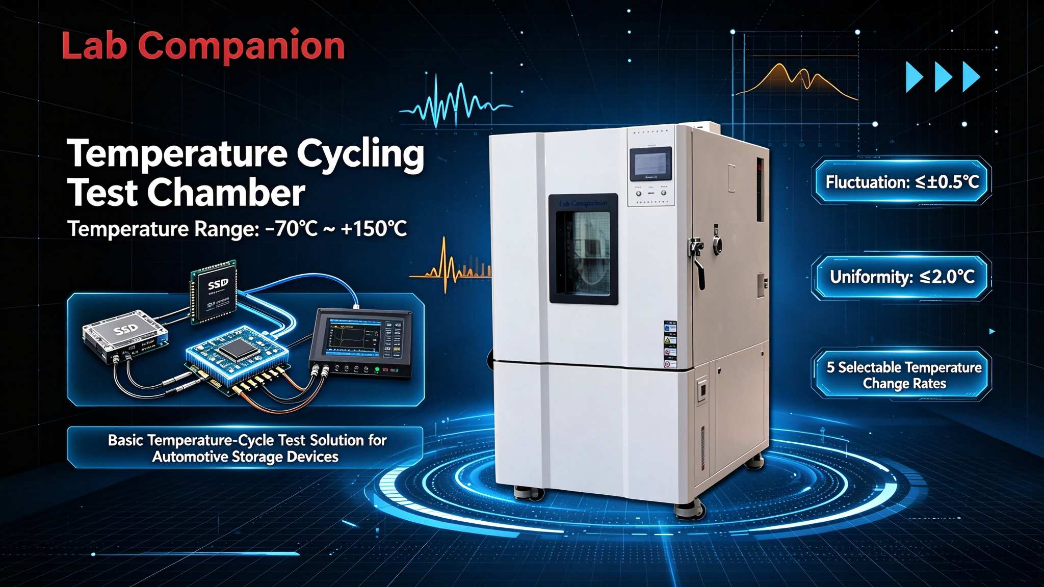
  • Lab Companion Temperature Cycling Chamber: AEC-Q100 Qualification Test Practice for Automotive eMMC / UFS / SSD
    Sep 09, 2026
    1. Practical Requirements of AEC-Q100 Qualification for Automotive Storage 1.1 Market Entry Barriers for Automotive-Grade Storage Driven by vehicle intelligence and connectivity, automotive storage devices are seeing rising adoption. Infotainment systems, instrument clusters, T-BOX units, ADAS domain controllers and autonomous driving domain controllers all rely on eMMC, UFS or automotive SSD for data storage. Unlike consumer storage, automotive storage directly impacts driving safety and user experience, requiring far higher reliability. Tier 1 suppliers and OEMs universally mandate AEC-Q100 reliability qualification for storage components during part selection. Products without this qualification cannot be admitted into automotive supply chains. AEC-Q100 is an IC stress test specification defined by the Automotive Electronics Council. It specifies a full suite of reliability tests for automotive ICs before mass release, including temperature cycling, high-temperature operating life, high temperature humidity bias, ESD and latch-up. Temperature cycling is one of the core tests. It verifies package integrity and solder joint fatigue life under repeated thermal swings. For automotive storage, temperature cycling results determine whether a product can pass AEC-Q100 and be listed in OEM approved vendor lists. 1.2 Position of AEC-Q100 in Storage Component Qualification AEC-Q100 classifies devices into four temperature grades based on operating temperature ranges for different vehicle applications: • Grade 3: 0℃ to +85℃ • Grade 2: -40℃ to +105℃ • Grade 1: -40℃ to +125℃ • Grade 0: -40℃ to +150℃ Grade 3 applies to less demanding in-cabin infotainment systems. Grade 2 covers body control, infotainment and T-BOX, which represent most automotive electronic modules. Grade 1 targets harsh environments near engine bays and ADAS domain controllers. Grade 0 serves the most demanding engine and transmission control units. For automotive storage, Grade 2 and Grade 1 are the mainstream qualification levels. Storage for infotainment and body control typically follows Grade 2. ADAS and autonomous driving storage, mounted close to engine compartments or requiring higher reliability margin, usually requires Grade 1. Temperature cycling is a mandatory AEC-Q100 test. Test conditions vary by grade: Grade 2 uses -40℃ to +105℃; Grade 1 uses -40℃ to +125℃. Both require a minimum of 500 cycles. 2. Comparison of Temperature Cycling Conditions: Grade 1 vs Grade 2 2.1 Grade 2: -40℃ ~ +105℃ Condition Breakdown Grade 2 temperature cycling spans -40℃ to +105℃ with a 145℃ delta. This profile simulates extreme real-world cabin conditions: vehicles parked outdoors in cold northern winters may drop near -40℃; after summer sun exposure, electronics behind dashboards can exceed 100℃. Each cycle consists of four phases: ramp from -40℃ to +105℃ (typically 10℃/min to 15℃/min), dwell at +105℃ for ≥10 minutes to stabilize internal sample temperature, ramp down from +105℃ to -40℃, then dwell at -40℃ for ≥10 minutes. One full cycle takes roughly 40–60 minutes. 500 cycles require continuous chamber operation for 330–500 hours (14–21 days). Samples remain powered during cycling, with real-time monitoring of read/write performance and key parameters. 2.2 Grade 1: -40℃ ~ +125℃ Condition Breakdown Grade 1 uses -40℃ to +125℃, creating a 165℃ temperature delta. Compared with Grade 2, the upper temperature limit rises by 20℃ and the thermal delta increases by 20℃. This profile targets storage mounted near engine bays and ADAS controllers, where component temperatures can exceed 105℃ and reach above 120℃ under heavy vehicle load. Raising the maximum temperature to 125℃ substantially increases stress on storage devices: 1. Larger thermal expansion mismatch across different materials creates stronger thermo-mechanical stress on solder joints and package interfaces, accelerating defect exposure. 2. 125℃ approaches the glass transition and creep range of molding compounds and solders, degrading mechanical properties and raising risks of solder fatigue and package delamination. 3. High temperatures accelerate NAND Flash data retention degradation, imposing stricter reliability requirements on storage media. The cycle sequence matches Grade 1 and Grade 2. However, the wider temperature delta extends ramp times. One Grade 1 cycle lasts 50–70 minutes. Completing 500 cycles requires continuous operation for 420–580 hours (18–24 days). 2.3 Test Differences and Selection Logic The core distinction between Grade 1 and Grade 2 lies in maximum temperature and thermal delta, which affects three areas: thermal stress magnitude, total test duration and chamber requirements. Grade 1 generates higher thermal stress and accelerates latent failure modes. Its total test time is 20–30% longer. The 125℃ plateau demands superior heating performance and temperature stability without overshoot. When defining qualification strategy, select the grade based on end application. Grade 2 is sufficient for infotainment, body control and T-BOX. Grade 1 is recommended for ADAS, autonomous driving controllers, engine-bay adjacent hardware, global markets or applications requiring extra reliability margin. A Grade 1 qualified component is backward compatible with Grade 2 use cases, while Grade 2 parts cannot be deployed in Grade 1 environments. Many manufacturers choose Grade 1 qualification upfront to broaden market coverage. 3. Full Workflow of Temperature Cycling Test 3.1 Pre-test: Sample Preparation and Initial Characterization AEC-Q100 temperature cycling includes three phases: pre-test preparation, test execution and post-test evaluation. Pre-test work ensures consistent sample condition and complete baseline data. A minimum of 77 units are randomly sampled from one batch (exact quantity depends on test plan and acceptance criteria). All samples undergo visual inspection to rule out physical damage, package defects or marking issues. Initial electrical characterization is then performed and recorded: functional tests (read/write, erase, bad block management), performance tests (sequential read/write speed, random IOPS), and health checks including SMART attributes, bad block count, wear leveling and initial error rates. Baseline data serves as reference for post-test comparison. Any meaningful parameter shift must be documented and analyzed. Only samples passing initial inspection are loaded into the chamber. Sample loading rules: distribute samples evenly across shelves to avoid localized thermal accumulation. Mount each unit on sockets or burn-in boards connected to external test hosts for live power monitoring. Maintain sufficient air gaps between samples to prevent airflow blockage and temperature non-uniformity. 3.2 Test Execution: Program Setup, Live Monitoring and Cycle Counting During execution, the chamber controller runs a programmed thermal profile: start temperature, ramp rate, high dwell setpoint and duration, low dwell setpoint and duration, plus target cycle count. Grade 2 is programmed for -40℃ / +105℃; Grade 1 for -40℃ / +125℃. Ramp rates are set between 10℃/min and 15℃/min, with minimum 10-minute dwells at extremes and 500 total cycles. Once started, the chamber runs automatically and continuously logs thermal profiles. External test hosts maintain power to DUTs and collect data every 5–10 minutes. Monitored items include power status, read/write integrity, disk dropouts, communication interruptions and abnormal error growth. Critical events such as DUT dropout are timestamped with cycle number. Cycle counting adopts dual control: automatic chamber logging plus daily manual cross-check against temperature curves to confirm validity. If tests stop due to power loss, chamber fault or temperature alarm, engineers review logs and thermal history to decide whether partial cycles count toward the total. AEC-Q100 defines clear rules for interrupted tests; all decisions must follow the standard. 3.3 Post-test: Final Characterization, Failure Analysis and Report Generation After finishing 500 cycles, samples are removed and stabilized for ≥2 hours under standard ambient conditions (15℃–35℃, 25–75% RH) before final testing. Final tests repeat the full initial inspection suite: visual check, functional, performance and health assessment. Acceptance criteria: no visible cracking, deformation or package damage; all read/write functions remain operational without dropouts or communication failures; performance degradation stays within product specification limits; bad block and error count increases remain within acceptable thresholds. Any failed unit triggers failure investigation. AEC-Q100 uses LTPD sampling to determine batch pass/fail based on failure tally. Failed samples go through failure analysis: SAM scanning for package delamination, X-ray inspection for solder cracking, cross-sectioning to observe crack morphology, and electrical fault isolation. FA findings feed design and process improvements. The final test report contains standard reference, test profile, chamber ID/calibration status, sample batch/serial numbers, baseline data, continuous temperature logs, cycle records, real-time monitoring logs, post-test results and failure analysis conclusions. Reports require sign-off by test and review engineers as supporting documentation for AEC-Q100 certification. 4. AEC-Q100 Compliance Capabilities of Lab Companion Temperature Cycling Chambers 4.1 Temperature Range and Accuracy Compliance Lab Companion temperature cycling chambers cover -70℃ ~ +150℃, fully satisfying AEC-Q100 Grade 2 (-40℃ to +105℃) and Grade 1 (-40℃ to +125℃) requirements with ample safety margin. The system maintains stable long-run operation at 125℃ without thermal drift. Performance specifications: temperature fluctuation ≤ ±0.5℃, temperature uniformity ≤2.0℃, temperature deviation ±2.0℃, exceeding GB/T 5170 requirements. AEC-Q100 requires consistent thermal stress across all DUTs. Lab Companion’s ≤2.0℃ uniformity ensures all automotive storage samples experience equivalent thermal loading over 500 cycles, delivering statistically valid test results. Linear ramp rates are configurable from 5℃/min to 25℃/min to precisely replicate AEC-Q100 thermal profiles. 4.2 Long-duration Stability and Data Traceability AEC-Q100 temperature cycling demands uninterrupted operation for 14–24 days. Lab Companion chambers use premium brand compressors and refrigeration components with multi-layer protection: over-temperature, compressor overload and phase-loss protection. Every unit undergoes a minimum 48-hour continuous run-in test before shipment to validate refrigeration and control reliability. Traceability is mandatory for AEC-Q100 audits. The touch controller automatically records temperature curves, cycle counters, alarms and runtime logs. Data can be exported via USB as CSV or PDF files for report archiving. Complete thermal logs serve as objective evidence during certification audits and meet traceability requirements. 4.3 Calibration at Dongguan Factory & Global Service Support Each chamber is assembled and calibrated at the Dongguan manufacturing site. Factory validation includes ramp rate verification, 9-point temperature mapping, extreme setpoint stability testing and continuous runtime validation. For automotive storage customers, pre-run validation for Grade 1 or Grade 2 profiles can be performed to confirm performance under your target test conditions. Delivery includes calibration certificates and validation reports, ready for lab system audits and AEC-Q100 on-site reviews. Our global service network delivers installation, commissioning, periodic calibration and on-site repair. Automotive qualification schedules are tight; rapid service response minimizes downtime caused by equipment faults. Annual maintenance is recommended, including refrigeration inspection, electrical tightening, thermal field recalibration and consumable replacement to sustain accuracy for years of AEC-Q100 testing. 5. Common Issues in AEC-Q100 Qualification and Mitigation 5.1 Test Interruption and Cycle Recounting Power outages, equipment faults or temperature alarms may halt cycling. AEC-Q100 interruption rules: if the stop occurs during temperature dwell, lasts ≤30 minutes and sample temperature remains close to setpoint, completed cycles remain valid. If interruption happens during ramp-up/ramp-down, or temperature deviates significantly, the incomplete cycle is discarded and valid counts must be re-evaluated against thermal logs. Mitigation: deploy UPS backup for power resilience; implement scheduled preventive maintenance; review temperature profiles and chamber status daily; preserve full logs after any outage and consult certification bodies when judging cycle validity. 5.2 Temperature Non-uniformity and Sample-to-sample Variation Poor airflow from overloading, accumulated dust or expired calibration creates uneven thermal distribution. Symptoms include large failure-rate variance across positions in one chamber and inconsistent results across batches. Mitigation: follow sample loading guidelines and preserve airflow channels; regularly clean condensers and air ducts; perform 9-point thermal mapping every 6–12 months to maintain ≤2.0℃ uniformity; mark poor-uniformity zones and avoid placing critical qualification samples there; arrange on-site service for airflow tuning and recalibration when needed. 5.3 Non-compliant Test Reports Auditors frequently reject incomplete reports due to missing ramp rates/dwell times, discontinuous temperature logs, unclear sample serial number traceability, superficial failure analysis or incomplete approval signatures. Mitigation: adopt standardized AEC-Q100 report templates covering all mandatory fields; export native chamber logs to avoid manual transcription errors; maintain sample traceability linking serial numbers, baseline data, runtime logs and post-test results; document full failure analysis for all rejected units; enforce three-level sign-off (test engineer, reviewer, approver). 6. Conclusion AEC-Q100 temperature cycling is a gatekeeper for automotive eMMC, UFS and SSD entering OEM supply chains. The difference between Grade 2 and Grade 1 defines thermal stress intensity, test duration and chamber requirements. Rigorous control across the full test lifecycle — sample preparation, in-test monitoring, post-test characterization and reporting — directly determines qualification success. Lab Companion temperature cycling chambers deliver wide temperature range, precise thermal control, reliable long-run operation and full data traceability, fully supporting AEC-Q100 Grade 1 and Grade 2 qualification for automotive storage. Backed by factory calibration in Dongguan and worldwide after-sales support, Lab Companion provides end-to-end solutions: chamber selection, profile setup and test execution support. We help storage manufacturers complete AEC-Q100 qualification smoothly and gain access to automotive supply chains.
    EN SAVOIR PLUS

  • Three-Level Verification System — Lab Companion Rapid Temperature Change Chamber: AI Compute Hardware Test Architecture
    Sep 09, 2026
    1. Hierarchical Testing Requirements for AI Compute Hardware 1.1 The Validation Gap from Silicon to Full Rack During R&D and mass production of AI compute hardware, a long-standing challenge exists: disconnected temperature validation across test layers. Traditionally, chip vendors perform thermal cycling and temperature testing at die level; board suppliers conduct functional and environmental validation on accelerator cards; server manufacturers run burn-in and stress tests at system level. However, these three tiers often adopt inconsistent standards and disjoint validation logic. Components that pass chip-level testing may suffer temperature-related failures at board level due to improper PCB thermal design. Even fully validated accelerator cards can encounter performance anomalies in full server racks caused by airflow interference and power fluctuation. This validation gap stems directly from the high power density of modern AI hardware. A single AI accelerator chip consumes 300W–700W, with stacked HBM memory creating localized hotspots. One accelerator card with multiple chips and high-capacity HBM reaches 500W–1000W. A complete AI server rack, housing dozens of cards, draws tens of kilowatts. Under such thermal loads, temperature is no longer a standalone environmental parameter, but a systemic variable spanning chips, boards and full racks. A tiered validation framework is required to guarantee thermal reliability at every layer. 1.2 Architecture of the Three-Level Test System Lab Companion establishes a progressive three-level rapid temperature change test system: Chip Level → Board Level → Full Rack Level. Each tier targets distinct specimens, equipment configurations, test profiles and validation priorities, while sharing one core objective: verifying thermal reliability across the entire stack of AI compute hardware. • Chip-level testing: validates thermal cycling tolerance of bare components, assessing packaging, solder joints and HBM stack integrity under rapid temperature transitions. • Board-level testing: evaluates thermal adaptability of accelerator cards, verifying PCB thermal layout, power delivery stability and cooling system performance. • Full rack-level testing: examines system-wide thermal management and multi-device coordination, validating airflow distribution, power allocation and cross-card performance consistency. Test conditions gradually mimic real operational environments. Validation focus evolves from component fatigue resistance to overall system stability, forming a complete thermal verification chain. 2. Chip-Level Rapid Temperature Change Testing 2.1 Test Specimens & Core Objectives Test items include AI accelerators (GPU / ASIC / NPU), HBM high-bandwidth memory, PMIC power management ICs, and high-speed SerDes / Retimer interface chips. These foundational components determine the stability of downstream boards and systems. Key validation goals: 1. Packaging reliability: Detect delamination, cracking and solder fatigue under rapid thermal cycling, with special focus on micro-bump interconnect integrity within HBM stacks. 2. Electrical stability: Monitor timing, power consumption and functional integrity during temperature ramps; verify signal integrity of high-speed interfaces. 3. Post-cycle performance consistency: Check whether computation throughput and power draw drift after repeated thermal cycles. 2.2 Equipment Selection: Small-Chamber High-Precision Models Chip testing involves high sample volumes in compact form factors, demanding tight temperature uniformity and control accuracy. Lab Companion TC series small-volume chambers (34L, 64L, 100L, 180L) are the preferred solution. Compact workspace enables fast thermal stabilization. High-precision variants achieve temperature fluctuation ≤ ±0.3°C and temperature uniformity ≤ ±0.5°C, ensuring hundreds of DUTs experience identical thermal profiles in one cycle. Chips are mounted on dedicated test sockets or burn-in boards secured by custom fixtures. Test cables pass through a port panel fitted with gaskets and thermal insulation to avoid cold leakage and temperature drift, enabling powered real-time monitoring connected to external testers. 2.3 Test Profiles & Parameter Setup Standard chip-level profiles follow JEDEC JESD22-A104 Condition C / G: • Temperature range: -40°C ~ +125°C or -55°C ~ +125°C • Ramp rate: 10°C/min ~15°C/min • Cycle count: 500 ~1000 cycles This profile effectively exposes thermomechanical fatigue in packaging and solder joints. For thermally sensitive devices such as HBM, temperature range and ramp speed can be adjusted per component specifications. Lab Companion TC series covers -70°C ~ +180°C. Five linear ramp rates are selectable: 5 /10 /15 /20 /25°C/min. The programmable touch controller defines multi-segment sequences (heat → high temp soak → cool → low temp soak). The chamber runs automatically and continuously logs temperature curves and alarms for full traceability. 3. Board-Level Rapid Temperature Change Testing 3.1 Test Specimens & Core Objectives Board-level DUTs cover GPU accelerator cards, ASIC inference cards, NPU training cards, AI server motherboards, high-speed switches and storage expansion cards. These populated boards integrate multiple chips, HBM and complex power networks, serving as the functional bridge between components and racks. Key validation goals: 1. PCB thermal design verification: Track temperatures of main die, HBM, PMIC and capacitors; identify hotspots during rapid temperature swings. 2. Power delivery stability: Evaluate output accuracy and dynamic response of multi-rail power supplies (core, HBM, I/O), preventing chip reset or functional failure induced by voltage noise. 3. Cooling system performance: Assess thermal behavior of onboard heatsinks, heat pipes and fans; check thermal throttling at high temperature and fan startup faults at low temperature. 3.2 Equipment Selection: Medium-Volume High-Load Models Accelerator cards are physically large and dissipate significant power when powered on. Lab Companion TC series medium-volume chambers (340L, 600L, 1000L) feature upgraded heating and refrigeration capacity, supporting thermal load ≥100kg aluminum equivalent for one or multiple powered accelerator cards under live workloads. Cards are vertically mounted using custom fixtures to replicate the original server orientation and airflow. External power supplies feed the DUT; PCIe signals are routed via extension cables to external test hosts or local onboard test motherboards. Feedthrough ports are thermally sealed for stable chamber conditions. 3.3 Test Profiles & Parameter Setup Board-level thermal profiles are less aggressive than chip-level stress tests: • Temperature range: -20°C ~ +70°C or 0°C ~ +70°C • Ramp rate: 5°C/min ~10°C/min • Cycle count: 100 ~500 cycles The goal is to validate board-level environmental adaptability rather than stimulate component packaging defects. At high-temperature soak, cards run full compute loads such as matrix operations and model inference to monitor die temperature, HBM temperature, power consumption and throughput. Low-temperature soak validates cold startup reliability. At ramp rates up to 15°C/min, temperature overshoot is controlled ≤ ±0.5°C, ensuring DUTs are not exposed to unintended thermal stress beyond defined limits. 4. Full Rack-Level Rapid Temperature Change Testing 4.1 Test Specimens & Core Objectives Full rack testing covers standalone AI servers, multi-node servers, full AI racks and liquid-cooled servers. This tier most closely replicates real data center deployment and validates system-level thermal management, power distribution and multi-card coordination. Key validation goals: 1. Airflow management: Detect airflow interference, hot air recirculation and concentrated hotspots across multiple servers and accelerator cards. 2. Rack power stability: Validate PDU and power module performance under thermal cycling, avoiding efficiency drop or protective shutdown triggered by temperature. 3. Cross-card performance consistency: Ensure uniform compute performance across all accelerators; prevent rack-wide training degradation caused by thermal throttling of individual cards. 4. Liquid cooling compatibility (if applicable): Verify sealing integrity and heat exchange efficiency of pipes, cold plates and quick-disconnect fittings under thermal cycling. 4.2 Equipment Selection: Large-Volume / Walk-In Custom Systems Standard chambers cannot accommodate full-size server racks with high power draw. Lab Companion TC series supports custom engineering from 80L up to 8000L, including large chambers and walk-in temperature rooms. • 1000L: suitable for single AI server testing • 2000L ~8000L walk-in rooms: designed for full racks or parallel multi-rack testing High-capacity heating/refrigeration offsets heat generated by live servers. Custom air ducts mimic hot aisle / cold aisle airflow of data centers, maintaining consistent inlet air temperature to servers. Reinforced flooring and heavy-duty fixtures support the weight of full server racks. 4.3 Test Profiles & Parameter Setup Full rack profiles simulate moderate temperature fluctuations inside data centers, with milder stress: • Temperature range: 10°C ~ +40°C or 15°C ~ +45°C • Ramp rate: 2°C/min ~5°C/min • Cycle count: 50 ~100 cycles The objective is not to induce component defects, but to evaluate dynamic thermal control response and sustained system stability. During high-temperature soak, full racks run heavy AI training or inference workloads. Monitored metrics include server inlet temperature, CPU/GPU junction temperature, power supply efficiency and total rack power draw. During temperature ramps, engineers track fan speed regulation, liquid cooling flow, temperature control response and performance consistency across all accelerators. Chamber refrigeration and airflow can be fully customized according to rack dimensions and power dissipation to guarantee stable thermal field and realistic air distribution. 5. Lab Companion’s Full-Scale Delivery Capability 5.1 Full Volume Matrix with Unified Standards Lab Companion TC rapid temperature change chambers deliver a complete volume matrix from 34L benchtop units up to 8000L walk-in custom rooms. One brand, consistent precision standards and unified service framework cover chip, board and full rack testing. Customers maintain identical operating workflows and comparable datasets across all three validation tiers, lowering maintenance and training costs. Performance specifications: • Temp fluctuation: ≤ ±0.5°C (high-precision version ≤ ±0.3°C) • Temp uniformity: ≤ ±2.0°C (high-precision version ≤ ±0.5°C) • Linear ramp: 5~25°C/min, optional LN₂ for 30°C/min • Temperature range: -70°C ~ +180°C This portfolio meets requirements ranging from component qualification to data center system simulation. 5.2 Customization & Calibration at Dongguan Manufacturing Base Lab Companion’s R&D and manufacturing center in Dongguan supports mass production of standard chambers plus custom engineering for walk-in systems up to 8000L. Custom options include dedicated card fixtures, high-speed signal feedthrough panels, high-power cable ports and data-center-style airflow designs tailored to AI hardware test requirements. Localized manufacturing shortens lead times compared with imported equipment, matching the fast iteration cycle of AI hardware. Every unit undergoes strict factory validation: ramp rate verification, 9-point temperature mapping, extreme setpoint stability test and long-duration continuous run. Large / walk-in systems additionally complete loaded thermal and airflow validation. Delivery includes full calibration certificates and test reports for lab audit and third-party certification. 5.3 Nationwide Service Network R&D labs and test facilities of AI hardware customers spread across China: Pearl River Delta, Yangtze River Delta, Beijing-Tianjin-Hebei region and western data centers. Lab Companion maintains regional service points for installation, commissioning, periodic calibration and repair. For large walk-in systems, field engineers manage on-site placement, utility connection, airflow tuning and thermal mapping. Annual preventive maintenance covers refrigeration inspection, electrical tightening, temperature calibration and consumable replacement. Remote diagnostics quickly troubleshoot common faults and reduce downtime. 6. Conclusion High power density makes AI compute hardware thermal reliability validation a multi-layer task rather than a single-stage test. Chip-level testing verifies thermomechanical fatigue of packaging and solder joints; board-level testing validates PCB thermal design and power integrity; full rack-level testing confirms system airflow and multi-card performance consistency. These tiers form an end-to-end thermal reliability validation chain. Lab Companion TC rapid temperature change chambers feature wide temperature range, high precision and scalable volume from small benchtop chambers to large walk-in custom rooms. With in-house Dongguan manufacturing and nationwide service support, Lab Companion provides unified thermal test solutions for chip designers, accelerator card vendors and server OEMs. We help customers build standardized, traceable three-level validation workflows and ensure thermal reliability of AI compute hardware through development to mass deployment.
    EN SAVOIR PLUS
  • Lab Companion Thermal Chamber: High-Low Temperature Testing for EV BMS and PV Inverters
    Sep 08, 2026
    1. Real-World Thermal Challenges for New Energy Electronic Components 1.1 Extreme Temperature Cycling in Field Operation New energy vehicles, photovoltaic power generation, and energy storage systems operate in fully exposed outdoor environments, where core electronic units endure drastic temperature swings from extreme cold to extreme heat. Reliability under wide temperature ranges is critical for system safety, efficiency, and service life. A Battery Management System (BMS) is installed inside vehicle battery packs. In cold regions, internal pack temperatures can drop below -20 °C or even -30 °C during winter parking. In summer, solar radiation plus fast-charging heat can raise internal temperatures above 50 °C. The BMS must maintain accurate temperature sampling, cell voltage monitoring, passive/active balancing, and stable communication across the entire operating temperature spectrum. PV inverters and Power Conversion Systems (PCS) face harsher ambient conditions. Desert summer cabinet temperatures can exceed 60 °C, while winter nights drop below -20 °C. Coastal regions combine high temperature with high humidity. Key components including IGBT modules, electrolytic capacitors, magnetic devices, and main control boards are highly temperature-sensitive. Excessive temperature deviation causes derating, over-temperature protection, reduced power generation efficiency, and unexpected system downtime. 1.2 Superimposed Heat Load from High-Power Operation Unlike conventional consumer electronics, new energy power devices generate significant internal heat during high-rate charging, discharging, and full-load operation. Inverters produce continuous high power loss through IGBT switching and conduction, creating steep thermal gradients inside enclosures. When internal heat buildup overlaps with high ambient temperature, component temperatures approach or exceed maximum ratings. For this reason, static temperature storage testing is insufficient. Real-world reliability verification requires dynamic, powered testing under temperature cycling. Chambers must support full-load operation, long-duration thermal stability, and real-time data monitoring to validate thermal derating, protection logic, and operational stability. 2. Standardized High/Low Temperature Test Items for BMS and Inverters 2.1 BMS Testing: Full-Range Temperature Accuracy & Control Stability BMS temperature testing focuses on data accuracy, cold-start reliability, and thermal balancing performance across extreme conditions. Low-temperature startup test: Soak at -20 °C to -40 °C before power-on to verify initialization, cell voltage and temperature sampling accuracy, and CAN communication stability under freezing conditions. High-temperature operational test: Continuous running at +60 °C to +85 °C under fast-charging and high-discharge load conditions. Engineers monitor temperature sampling error, over-temperature protection thresholds, and balancing current stability. Temperature accuracy is fundamental for SOC estimation, charge/discharge cutoff control, and fault protection. Minor sampling deviations may lead to incorrect battery strategy and potential safety risks. Lab Companion chambers support precise point-to-point calibration across -40 °C to +85 °C to validate BMS algorithm robustness. 2.2 PV Inverter & PCS Testing: Full-Load Stability & Thermal Derating Verification Inverter testing emphasizes full-load operational reliability and temperature-based derating characteristics under extreme ambient conditions. High-temperature full-load test: Operate at rated DC input and full AC output for minimum 4 hours at +40 °C to +60 °C. Monitor IGBT junction temperature, capacitor temperature, control board temperature, system efficiency, THD, voltage/frequency stability, and over-temperature protection behavior. Validated results ensure no unexpected derating or shutdown within specified temperature limits. Low-temperature performance test: Verify cold-start capability and low-load stability at -20 °C to -40 °C. Low temperatures cause capacitance drop and ESR increase in electrolytic capacitors, which may induce bus voltage fluctuation. Tests confirm reliable startup, normal grid-tie/off-grid switching, and no false alarms in cold environments. 2.3 Global Compliance Standards All test procedures comply with internationally recognized standards, including IEC 60068-2-1 / IEC 60068-2-2, GB/T 2423, as well as industry-specific specifications for BMS (QC/T 897, GB/T 31467) and inverters (NB/T 32004, GB/T 37408, GB/T 34120). 3. Lab Companion Chamber Technical Advantages for New Energy Testing 3.1 Full Volume Range for High-Power Device Testing Lab Companion thermal chambers cover a full volume range from 34 L to 1500 L, fully matching new energy testing requirements. Medium and large chambers (340 L–1500 L) are specially optimized for high-calorific and heavy-load samples such as BMS units, onboard controllers, PV inverters, and energy storage PCS systems. Enhanced heating and cooling systems guarantee rapid temperature recovery and uniform thermal field even with high-power heat-generating DUTs. SUS304 stainless steel interior provides corrosion resistance against electrolyte vapor and industrial dust. Customizable shelf spacing and load-bearing structures ensure stable sample placement and unobstructed internal airflow. 3.2 Ultra-Wide Temperature Range & High Precision Stability Lab Companion chambers feature a wide temperature range of -70 °C to +150 °C, with customizable low-temperature thresholds to match different project specifications. The operational range fully covers standard BMS and inverter test boundaries with sufficient safety margin for long-term stable operation. Precision performance meets strict industrial testing requirements: Temperature fluctuation ≤ ±0.5 °C, temperature uniformity ≤ ±2.0 °C (high-precision version ≤ ±0.3 °C). Equipped with proprietary Q8 intelligent control system and balanced temperature & humidity control (BTHC) technology, the chamber avoids temperature overshoot and oscillation, delivering consistent, repeatable thermal conditions for accurate algorithm calibration and reliability validation. 3.3 Customized Cable Ports for Powered & Live Testing All Lab Companion environmental chambers support customized insulated cable ports for power cables, CAN/RS485 communication lines, and sensor wiring. The sealed and insulated port design prevents cold leakage and thermal field disturbance during long-duration powered tests. Customers can perform real-time data acquisition including BMS cell voltage, temperature sampling error, SOC balance status, and fault logs. For inverters, users can connect external DC power sources and AC load banks to conduct full-load continuous aging and thermal derating testing, with complete data logging and export functions for technical reports and certification documents. 4. Global Service & Technical Support Model 4.1 Factory Direct Customization & Global Delivery Lab Companion is a national high-tech enterprise and specialized & sophisticated manufacturer based in Dongguan, China. With 21 years of experience in environmental test equipment R&D and manufacturing, the brand holds Madrid International Trademark registration, as well as EU, UK, and Germany trademark certifications, supporting global project qualification and customer recognition. We provide worldwide direct shipping and factory customization services, including customized internal dimensions, high-power port configurations, special load-bearing shelves, and tailored thermal solutions for customer-specific inverter and BMS test standards. 4.2 Global Online Remote Technical Support To serve global customers efficiently, Lab Companion adopts an overseas online support system. We do not provide local after-sales service teams in foreign countries, but deliver full-life-cycle remote technical support. Our professional international support team providesonline installation guidance, operation training, parameter calibration, program debugging, and remote fault diagnosis. Most technical issues can be resolved efficiently via online guidance, eliminating regional service barriers and ensuring stable and continuous equipment operation for global laboratories and factories. 4.4 Global Industry Application Cases Lab Companion thermal test chambers are widely used in global new energy vehicle, photovoltaic, and energy storage industries. Our equipment has been adopted by automotive electronics suppliers, renewable energy manufacturers, and university research institutions for BMS temperature calibration, inverter high-low temperature cycling, full-load aging, and thermal derating validation. Stable temperature accuracy and reliable long-duration operation help customers optimize product algorithms, improve extreme environmental adaptability, and accelerate product certification and mass production. 5. Conclusion Extreme temperature adaptability is a core indicator of reliability for EV BMS, PV inverters, and energy storage converters. Professional high-low temperature testing is essential for product R&D, performance optimization, and global market certification. Lab Companion environmental test chambers provide ultra-wide temperature range, high-precision thermal stability, high-load compatibility, and customizable powered test interfaces, perfectly matching the full-cycle reliability testing needs of new energy power electronic products. Supported by factory direct customization and professional global remote technical support, we deliver stable, cost-effective, and standardized thermal testing solutions for global new energy enterprises, helping customers enhance product durability and market competitiveness in all-climate operating scenarios.
    EN SAVOIR PLUS
  • Lab Companion Thermal Cycling Test Chambers: Application Practice for Optical Modules and Passive Optical Components Lab Companion Thermal Cycling Test Chambers: Application Practice for Optical Modules and Passive Optical Components
    Sep 07, 2026
    1. Core Challenges: Temperature Sensitivity of Optical Communication Components 1.1 Optical Parameter Drift Caused by Temperature Change Optical communication components are far more temperature-sensitive than conventional electronic devices. Temperature fluctuation directly shifts key optical parameters and degrades system transmission performance. For active optical modules, DFB laser wavelength drifts approximately 0.1 nm per °C. When temperature rises from 0 °C to 70 °C, the total wavelength shift can exceed 7 nm. Once the drift exceeds the channel spacing of WDM systems, crosstalk and bit error rate will increase significantly. Meanwhile, temperature variation changes laser threshold current, output optical power and extinction ratio, causing unstable emission performance at extreme temperatures. Passive optical devices also suffer from severe temperature-dependent drift. AWG devices based on PLC technology feature a high thermo-optic coefficient of 1.8×10⁻⁴/°C. Temperature change alters the effective refractive index of waveguides and shifts the central wavelength. Uncompensated AWG modules can drift several nanometers across −40 °C to +85 °C. In addition, temperature fluctuation changes insertion loss of optical splitters and return loss of fiber connectors. Therefore, full-range thermal cycling testing is essential to verify stable optical performance. 1.2 Packaging Reliability Risks Under Thermal Cycling Repeated temperature changes generate thermo-mechanical stress inside optical components. An optical module consists of multiple materials including laser chips, detectors, lenses, isolators, ceramics, metal shells and PCB substrates. Different thermal expansion coefficients create shear stress at bonding and soldering interfaces during temperature cycling. Long-term thermal cycling may lead to optical misalignment, bonding failure or solder crack issues. For fiber-coupled devices, submicron alignment precision is extremely sensitive to tiny structural deformation. Even minor displacement can reduce coupling efficiency. For this reason, continuous thermal cycling testing is a mandatory reliability procedure for optical components before mass production. 2. Global Standards and Test Specifications for Optical Thermal Cycling 2.1 International Standard Framework Telcordia GR-468-CORE serves as the primary guideline for optical component reliability testing. It defines thermal cycling as a critical qualification item. Standard test conditions cover −40 °C to +85 °C with a minimum of 500 cycles for commercial products. For high-reliability scenarios such as outdoor base stations and industrial equipment, 1000 cycles are required. Tests also comply with IEC 60068-2-14 Nc temperature variation standards. For high-speed data center optical modules, design and reliability requirements follow SFF-8431 and SFF-8432 MSA specifications. All optical and electrical parameters must remain within acceptable tolerance after long-cycle temperature shocks. 2.2 Standard Test Profiles and Operation Requirements The industry-standard temperature range is −40 °C to +85 °C, extended to −40 °C to +105 °C for industrial-grade products. A complete cycle includes four stages: low-temperature soaking, linear heating, high-temperature soaking, and linear cooling. Soaking time at extreme temperatures is no less than 15 minutes to ensure full temperature stabilization inside components. Typical ramp rate ranges from 5 °C/min to 15 °C/min. Long-duration testing requires continuous and stable equipment operation. 500 cycles take approximately 40 days of non-stop running, while 1000 cycles take up to 80 days. Any temperature instability or system interruption will invalidate test data. Stable chamber performance is critical for mass qualification. 2.3 In-Situ Optical Parameter Monitoring Different from general electronic testing, optical component qualification requires real-time optical parameter monitoring during temperature cycling. Active modules require continuous monitoring of optical power, extinction ratio, eye diagram quality, receiver sensitivity and operating current. Passive devices require testing of insertion loss, return loss, wavelength shift and PDL. Real-time measurement requires external connection to optical power meters, spectrum analyzers and BER testers through fiber feedthrough ports. The feedthrough design must ensure effective sealing and thermal insulation to avoid cold leakage, internal frosting and temperature fluctuation. Lab Companion provides customizable multi-channel fiber feedthrough panels to support stable long-cycle optical monitoring. 3. Lab Companion Thermal Cycling Chamber: Optimized for Optical Industry Testing 3.1 Ultra-Wide Temperature Range and High Precision Stability Lab Companion thermal cycling chambers cover a temperature range from −70 °C to +150 °C, fully exceeding GR-468 standard requirements. The wide temperature margin ensures stable operation even during months of continuous cycling, without running at extreme load limits. The chamber achieves temperature fluctuation ≤ ±0.5 °C and temperature uniformity ≤ 2.0 °C, delivering far higher stability than standard requirements. The optimized air duct circulation system ensures uniform temperature distribution across the entire workspace. It eliminates data deviation caused by local temperature difference and guarantees accurate, repeatable optical performance evaluation. 3.2 Adjustable Ramp Rates and Dual Operation Modes Lab Companion equipment supports five adjustable ramp rates: 5 °C/min, 10 °C/min, 15 °C/min, 20 °C/min and 25 °C/min. Both linear and non-linear temperature profiles are available. Linear mode strictly follows IEC and GR-468 standard curves for official certification and cross-lab data comparison. Non-linear mode simulates real-world environmental temperature changes for accelerated reliability verification in R&D stages. For high-stress screening, optional liquid nitrogen auxiliary cooling increases the maximum cooling rate to 30 °C/min, greatly improving mass testing efficiency. 3.3 Multi-Size Chamber and Customized Fixture Solutions Optical components feature small size and large batch testing demands. Lab Companion provides multiple chamber volumes: 80 L, 150 L and 225 L for R&D and small-batch qualification; 340 L and 600 L models for high-volume mass production screening. Multi-layer racks support simultaneous testing of hundreds of optical modules and passive components. Customized fixtures are available for optical-specific applications. SFP/QSFP module test brackets support independent power supply and high-speed signal connection for real-time BER testing. Dedicated fiber management trays protect AWG and splitter fibers from excessive bending stress. SUS304 stainless steel inner chamber ensures high cleanliness and long-term durability. 4. Localized Manufacturing and Global Service Support 4.1 Customized Manufacturing and Fast Delivery Founded in 2005, Lab Companion (Guangdong Hongzhan Technology) is a national high-tech enterprise and specialized & sophisticated manufacturer based in Dongguan, China. It is strategically located near the optical communication industrial clusters of Shenzhen and Guangzhou, enabling fast customized solutions and short lead-time delivery. All chambers undergo strict factory calibration, including 9-point temperature uniformity testing, ramp rate verification and long-cycle stability validation. Before delivery, optical test-oriented optimization and feedthrough sealing performance testing ensure full compliance with customer qualification standards. 4.2 Global Service Network for Long-Term Stable Operation Optical reliability tests require weeks or months of non-stop operation. Equipment stability and rapid after-sales support are essential. Lab Companion operates 16 service centers across China and overseas support networks, providing fast response, on-site debugging, calibration and maintenance services. Remote diagnosis functions quickly identify temperature control errors and sensor faults. Annual maintenance programs include refrigeration system inspection, electrical tightening, temperature field recalibration and wearing part replacement, ensuring long-term precision and stability during continuous cycling tests. 4.3 Verified Field Application Results Lab Companion thermal cycling chambers are widely adopted by optical module manufacturers, passive component suppliers and communication equipment enterprises. The equipment stably supports more than 500 consecutive thermal cycles with consistent temperature accuracy and reliable ramp rate control. The sealed fiber feedthrough design effectively prevents cold leakage and internal frosting during long-term optical monitoring. Custom fixtures ensure standardized sample placement and safe fiber routing. Customers obtain complete full-temperature optical performance curves to optimize temperature compensation algorithms and packaging structures, improving product reliability for 5G, data center and outdoor communication applications. 5. Conclusion Thermal cycling testing is an indispensable procedure for optical component reliability qualification. It effectively exposes wavelength drift, power attenuation, insertion loss variation and packaging structural risks under alternating temperature conditions, fully meeting GR-468, IEC and GB/T standard requirements. Lab Companion thermal cycling test chambers provide ultra-wide temperature range, high-precision temperature control, multi-speed ramp adjustment and professional optical test customization capabilities. The dedicated fiber feedthrough structure and customized fixture system solve the core difficulties of real-time optical monitoring during dynamic temperature cycling. Backed by 21 years of professional R&D and manufacturing experience, localized customization capability and global after-sales service network, Lab Companion delivers one-stop test solutions for optical communication customers. It helps enterprises build standardized and traceable reliability test systems, ensuring stable and durable performance of optical modules and passive components in global 5G and data center infrastructure applications.
    EN SAVOIR PLUS
  • Lab Companion Temperature Test Chambers: Full-Lifecycle SSD Testing Solutions from R&D to Mass Production Screening
    Sep 04, 2026
    1. SSD Reliability Testing: More Than Basic Temperature Simulation Solid-state drives (SSDs) undergo rigorous environmental reliability validation throughout their entire journey from prototype design to mass delivery. Every development stage demands distinct testing standards: performance boundary verification in R&D, standard compliance validation in design verification, process stability evaluation during pilot production, and early failure screening in mass manufacturing. Each phase requires different equipment capabilities. R&D requires ultra-wide temperature range and high-precision control to capture accurate limit performance data. Design verification prioritizes test repeatability and consistency. Pilot production needs scalable batch testing capacity. Mass production demands high throughput, automated operation, and long-term stable runtime performance. A single versatile test chamber that covers the full development lifecycle greatly improves testing efficiency and reduces equipment investment costs. Established in 2005, Lab Companion is a national high-tech enterprise and specialized & sophisticated manufacturer based in Dongguan, China. With 20+ years of focus on environmental reliability test equipment, our PS series temperature and humidity chambers and TC series rapid thermal cycling chambers serve as one-stop testing platforms for consumer and enterprise-grade SSD full-lifecycle validation. 2. R&D Phase: Performance Boundary Exploration Under Extreme Conditions During SSD prototype development, engineers must verify the operational stability of main controllers, NAND flash particles, and complete drives across diverse temperature environments. Small-batch engineering samples require wide-spectrum temperature testing with strict precision requirements. Lab Companion PS series thermal test chambers feature a broad temperature range of-70℃ to +150℃. This fully covers consumer SSD testing scenarios from -10℃ cold startup to +70℃ high-temperature continuous read-write operation. It also meets enterprise SSD thermal cycling standards (40℃ to 85℃) and reserves sufficient margin for vehicle-grade SSD extreme validation (-40℃ to 125℃). The chamber delivers industry-leading precision: temperature fluctuation ≤±0.5℃, temperature deviation ≤±2.0℃, and temperature uniformity ≤±2.0℃. Compliant with the GB/T 10592-2023 international equipment standard, it ensures uniform environmental stress across all sample positions and highly repeatable test results. For advanced R&D validation, Lab Companion chambers support docking with Advantest and Teradyne IC test systems to verify core chip functionality under extreme temperatures. External T/K-type thermocouples accurately monitor real sample surface temperatures, ensuring precise thermal soak validation. 3. DVT Phase: Standard Compliance and Repeatable Validation In the Design Verification Test (DVT) stage, SSD products must comply with global JEDEC industry standards, includingJESD218 and JESD22-A104. Consumer SSDs undergo 25℃ to 70℃ thermal cycling to simulate daily usage and verify stability and data integrity. Enterprise SSDs require 40℃ to 85℃ cycling with 100% random read-write load to validate QoS latency consistency under high-load operation. DVT testing requires outstanding equipment repeatability to eliminate environmental errors from batch-to-batch results. Lab Companion’s stable temperature control ensures identical test conditions for every cycle. The programmable controller stores multiple custom test profiles for automatic cyclic operation, minimizing human-induced variables. For long-duration durability tests requiring hundreds or thousands of thermal cycles, Lab Companion chambers support 1000+ hours of continuous stable operation. Built-in UPS power backup and breakpoint resume functions automatically restore testing after unexpected power outages, preventing sample damage and data loss. 4. PVT Phase: Mass Production Process Stability Verification During Pilot Verification Test (PVT), manufacturers validate mass-production process consistency via medium-batch sample testing. Reliable batch thermal cycling results are critical for confirming production yield stability. Lab Companion chambers adopt a flexible multi-layer tray structure adaptable to various SSD dimensions. Standard volume options range from 80L to 1000L, with custom capacities from 80L to 8000L available to suit lab-scale R&D and medium-volume pilot testing. Each SSD sample supports independent power supply and individual data monitoring. The system automatically records full-test data including temperature curves, ramp rates, and dwell time, and generates standardized pass/fail test reports. All data can be integrated into factory quality traceability systems to support mass production validation decisions. 5. Mass Production Phase: High-Efficiency Stress Screening and Early Failure Elimination High-volume SSD mass production requires fast, cost-effective reliability screening to eliminate early failed units without compromising throughput. Lab Companion ESS Environmental Stress Screening Chambers are purpose-built for production-line accelerated testing. The ESS series provides adjustable thermal ramp rates of 5℃/min to 15℃/min within -55℃ to +85℃, with temperature uniformity ≤2℃. Pre-configured standard test profiles allow one-click switching between consumer and enterprise SSD screening procedures. The multi-layer tray design enables high-density simultaneous testing of hundreds of SSDs. Equipped with independent power and data acquisition channels, the system supports 24/7 unattended automated operation, significantly improving production-line testing efficiency. In practical industrial applications, a Tier 1 automotive supplier reduced SSD early failure rate from 800ppm to below 200ppm after deploying the Lab Companion TC-408 rapid thermal cycling chamber (10℃/min ramp rate), demonstrating reliable mass-screening performance. 6. Full-Cycle Safety Protection and Complete Data Traceability High-value SSD prototypes and mass-production components require rigorous safety protection and full data traceability throughout testing. Lab Companion chambers adopt multi-level safety mechanisms: independent mechanical over-temperature protection (hardware-level cutoff unaffected by software failures), compressor over-pressure/overload/delay startup protection, dual over-temperature protection for heating systems, and comprehensive electrical protection against phase loss, leakage, and grounding faults. These designs fully protect test samples from damage. For quality management, the system supports batch code scanning and full-process data archiving. All temperature curves, test parameters, and operation logs are permanently traceable. Intelligent fault diagnosis displays error codes and troubleshooting steps directly on the screen, with remote alarm notifications available via mobile and PC terminals for unattended operation security. 7. Conclusion Reliability temperature testing runs through the entire SSD lifecycle: R&D boundary exploration, DVT standard compliance verification, PVT process validation, and mass production failure screening. With -70℃ to +150℃ ultra-wide temperature range, ±0.5℃ precise temperature control, excellent temperature uniformity, and scalable batch testing capability, Lab Companion PS and TC series chambers deliver a fully compatible solution for SSD industry from laboratory R&D to factory mass production. Serving over 3000 global manufacturers, research institutions and testing labs, Lab Companion has proven its capability as a reliable full-lifecycle testing partner for semiconductor storage reliability validation.
    EN SAVOIR PLUS
  • Lab Companion MES/EAP-Enabled Temperature Test Chambers: Quantifiable Improvements in Efficiency, Cost, Quality and Factory Management
    Sep 03, 2026
    1. Overview: Turning Reliability Testing from “Cost Center” into “Data Asset” In semiconductor, automotive electronics, new energy and optical communication manufacturing, environmental reliability testing has long been treated as a necessary cost. Traditional temperature chambers operate as standalone devices. Test data is stored locally, isolated from factory systems, and requires heavy manual work to organize and verify. Lab Companion network-enabled temperature and thermal cycling chambers solve this industry pain point. By supporting MES and EAP system integration, our testing equipment becomes a connected node on the smart production line. All test data is digitized, traceable and automatically synchronized to factory management systems. The upgrade delivers clear, quantifiable improvements in productivity, operational cost, quality compliance and factory transparency. 2. Efficiency Gains: Automate Manual Workflows Most testing bottlenecks are not caused by device performance, but by repetitive manual operations: recipe setup, batch entry, data logging and report generation. Lab Companion smart chambers eliminate these inefficient workflows. 2.1 One-click standard test recipes Equipped with an industrial H-Touch controller, the chamber supports up to 1200 programmable cycling segments. Industry-standard test profiles including JESD22-A104, JESD22-A106B and AEC-Q100 are preloaded and available for one-click activation. Manufacturers no longer need manual parameter configuration during product changeover. It eliminates human setup errors, avoids invalid testing and shortens setup time significantly. 2.2 Auto batch logging and PDF report output The device supports barcode batch scanning for automatic product binding. Once a test completes, the system automatically generates a standardized PDF report containing temperature curves, ramp rates, dwell time and pass/fail results. All data is uploaded directly to MES. This replaces manual report sorting, which traditionally takes around 40 minutes per batch, saving substantial labor hours for mass production. 2.3 Local real-time data recording and direct USB export Real-time test curves are automatically saved locally. Operators can export complete historical data via USB without extra host software. Data retrieval and technical review become fast and convenient. 3. Cost Reduction: Lower Energy Consumption & Maintenance Cost For 24/7 continuous environmental screening, energy consumption and equipment maintenance are the two largest operational costs. Lab Companion optimizes both through intelligent control and upgraded hardware. 3.1 AI energy-saving control, 28%–38% power reduction Traditional on-off compressors waste massive energy during stable temperature holding. Lab Companion chambers adopt variable-frequency compressors + electronic expansion valves, paired with self-developed Q8 intelligent control algorithm. The system dynamically adjusts compressor frequency, heating output and airflow based on real-time load and ambient conditions. Temperature overshoot is controlled below 0.8%. Compared with conventional chambers, overall energy consumption drops by 28%–38%, and steady-state power saving exceeds 40%. 3.2 AI predictive fault diagnosis, 70% fewer failures Traditional maintenance is passive and reactive. Lab Companion’s real-time component monitoring system predicts potential failures in advance. Data shows the intelligent warning system reduces equipment failure rate by 70% and cuts maintenance costs by 30%. The built-in 600,000 offline data storage points ensure zero data loss during network disconnection. Data will be auto-resynchronized once the network recovers, preventing rework caused by missing records. 4. Quality Upgrade: Full Lifecycle Traceability & Compliance For high-precision industries, reliable, auditable and reproducible test data is the core of quality certification and supply-chain compliance. 4.1 Complete data chain from batch to final judgment Via OPC UA and Modbus TCP protocols, the chamber synchronizes all test parameters to MES in real time, including temperature profiles, cycling speed, holding duration and pass/fail status. It builds a full traceability chain: Batch — Device — Recipe — Curve — Test Result. 4.2 No manual filling for audit and certification All data is automatically archived with unified standards. No manual spreadsheet adjustment is required before customer audits or industry certification reviews. It greatly reduces compliance risks and preparation workload. 4.3 Stable data recording for long-duration tests With 600,000 offline storage records, the system supports ultra-long aging and cycling tests for optical components and new energy cells. Continuous data integrity is guaranteed even under unstable network conditions. 5. Smart Factory Management: Transparent & Remote Operation Standalone test chambers create “black boxes” on production lines. Lab Companion networking transforms discrete testing equipment into visible, manageable production assets. 5.1 Real-time test progress visualization MES management terminals can monitor real-time status of all connected chambers, including running recipes, test progress and completion results. Production supervisors can schedule tasks accurately and optimize equipment utilization. 5.2 Full remote monitoring & control Based on web-based Q8 control system, engineers can remotely view temperature curves, adjust parameters, start/stop tests and check historical records via PC or mobile devices. On-site attendance is no longer mandatory, which greatly improves management efficiency for multi-site factories. 5.3 Instant alarm for abnormal status System errors and parameter deviations trigger real-time alerts. Maintenance teams can respond rapidly to minimize downtime and ensure continuous production screening. 6. Core Specifications of Lab Companion Networked Test Chambers • Product Series: TC/ESS Rapid Temperature Change Chamber, TS/PS Temperature & Humidity Chamber, OVEN High-Temperature Aging Chamber • Temperature Range: -70℃ ~ +150℃; max +300℃ for high-temp models • Temperature Accuracy: Fluctuation ±0.5℃, Deviation ±2.0℃, Uniformity ≤2.0℃ • Temperature Ramp Rate: 5℃/min ~ 25℃/min optional • Capacity Range: 80L ~ 2000L full coverage • Standard Interface: RS485, Ethernet • Industrial Protocols: OPC UA / Modbus TCP optional; SECS/GEM customizable for semiconductor FAB EAP integration • Smart Functions: 1200-step programmable recipes, 600,000 offline data storage, AI predictive maintenance, remote control 7. Conclusion: Measurable Benefits for Smart Manufacturing Lab Companion MES/EAP-enabled environmental test chambers deliver fully verified, data-driven upgrades for modern factories: • Higher Efficiency: Automated recipes, auto-reporting and barcode tracing eliminate repetitive manual work and human errors. • Lower OPEX: 28%–38% energy saving and 30% less maintenance cost bring long-term operational benefits. • Reliable Quality: Full-process traceable data meets global automotive, semiconductor and new energy certification standards. • Digital Management: Transparent, remote and intelligent operation fits Industry 4.0 smart factory requirements. Proven in semiconductor, automotive electronics, optical communication and new energy production lines, Lab Companion networked testing solutions help global manufacturers turn reliability testing from a pure cost center into a valuable, data-driven quality control asset.
    EN SAVOIR PLUS
  • Lab Companion MES/EAP-Enabled Temperature Test Chambers: Quantifiable Improvements in Efficiency, Cost, Quality and Factory Management Lab Companion MES/EAP-Enabled Temperature Test Chambers: Quantifiable Improvements in Efficiency, Cost, Quality and Factory Management
    Sep 02, 2026
    1. Overview: Turning Reliability Testing from “Cost Center” into “Data Asset” In semiconductor, automotive electronics, new energy and optical communication manufacturing, environmental reliability testing has long been treated as a necessary cost. Traditional temperature chambers operate as standalone devices. Test data is stored locally, isolated from factory systems, and requires heavy manual work to organize and verify. Lab Companion network-enabled temperature and thermal cycling chambers solve this industry pain point. By supporting MES and EAP system integration, our testing equipment becomes a connected node on the smart production line. All test data is digitized, traceable and automatically synchronized to factory management systems. The upgrade delivers clear, quantifiable improvements in productivity, operational cost, quality compliance and factory transparency. 2. Efficiency Gains: Automate Manual Workflows Most testing bottlenecks are not caused by device performance, but by repetitive manual operations: recipe setup, batch entry, data logging and report generation. Lab Companion smart chambers eliminate these inefficient workflows. 2.1 One-click standard test recipes Equipped with an industrial H-Touch controller, the chamber supports up to 1200 programmable cycling segments. Industry-standard test profiles including JESD22-A104, JESD22-A106B and AEC-Q100 are preloaded and available for one-click activation. Manufacturers no longer need manual parameter configuration during product changeover. It eliminates human setup errors, avoids invalid testing and shortens setup time significantly. 2.2 Auto batch logging and PDF report output The device supports barcode batch scanning for automatic product binding. Once a test completes, the system automatically generates a standardized PDF report containing temperature curves, ramp rates, dwell time and pass/fail results. All data is uploaded directly to MES. This replaces manual report sorting, which traditionally takes around 40 minutes per batch, saving substantial labor hours for mass production. 2.3 Local real-time data recording and direct USB export Real-time test curves are automatically saved locally. Operators can export complete historical data via USB without extra host software. Data retrieval and technical review become fast and convenient. 3. Cost Reduction: Lower Energy Consumption & Maintenance Cost For 24/7 continuous environmental screening, energy consumption and equipment maintenance are the two largest operational costs. Lab Companion optimizes both through intelligent control and upgraded hardware. 3.1 AI energy-saving control, 28%–38% power reduction Traditional on-off compressors waste massive energy during stable temperature holding. Lab Companion chambers adopt variable-frequency compressors + electronic expansion valves, paired with self-developed Q8 intelligent control algorithm. The system dynamically adjusts compressor frequency, heating output and airflow based on real-time load and ambient conditions. Temperature overshoot is controlled below 0.8%. Compared with conventional chambers, overall energy consumption drops by 28%–38%, and steady-state power saving exceeds 40%. 3.2 AI predictive fault diagnosis, 70% fewer failures Traditional maintenance is passive and reactive. Lab Companion’s real-time component monitoring system predicts potential failures in advance. Data shows the intelligent warning system reduces equipment failure rate by 70% and cuts maintenance costs by 30%. The built-in 600,000 offline data storage points ensure zero data loss during network disconnection. Data will be auto-resynchronized once the network recovers, preventing rework caused by missing records. 4. Quality Upgrade: Full Lifecycle Traceability & Compliance For high-precision industries, reliable, auditable and reproducible test data is the core of quality certification and supply-chain compliance. 4.1 Complete data chain from batch to final judgment Via OPC UA and Modbus TCP protocols, the chamber synchronizes all test parameters to MES in real time, including temperature profiles, cycling speed, holding duration and pass/fail status. It builds a full traceability chain: Batch — Device — Recipe — Curve — Test Result. 4.2 No manual filling for audit and certification All data is automatically archived with unified standards. No manual spreadsheet adjustment is required before customer audits or industry certification reviews. It greatly reduces compliance risks and preparation workload. 4.3 Stable data recording for long-duration tests With 600,000 offline storage records, the system supports ultra-long aging and cycling tests for optical components and new energy cells. Continuous data integrity is guaranteed even under unstable network conditions. 5. Smart Factory Management: Transparent & Remote Operation Standalone test chambers create “black boxes” on production lines. Lab Companion networking transforms discrete testing equipment into visible, manageable production assets. 5.1 Real-time test progress visualization MES management terminals can monitor real-time status of all connected chambers, including running recipes, test progress and completion results. Production supervisors can schedule tasks accurately and optimize equipment utilization. 5.2 Full remote monitoring & control Based on web-based Q8 control system, engineers can remotely view temperature curves, adjust parameters, start/stop tests and check historical records via PC or mobile devices. On-site attendance is no longer mandatory, which greatly improves management efficiency for multi-site factories. 5.3 Instant alarm for abnormal status System errors and parameter deviations trigger real-time alerts. Maintenance teams can respond rapidly to minimize downtime and ensure continuous production screening. 6. Core Specifications of Lab Companion Networked Test Chambers • Product Series: TC/ESS Rapid Temperature Change Chamber, TS/PS Temperature & Humidity Chamber, OVEN High-Temperature Aging Chamber • Temperature Range: -70℃ ~ +150℃; max +300℃ for high-temp models • Temperature Accuracy: Fluctuation ±0.5℃, Deviation ±2.0℃, Uniformity ≤2.0℃ • Temperature Ramp Rate: 5℃/min ~ 25℃/min optional • Capacity Range: 80L ~ 2000L full coverage • Standard Interface: RS485, Ethernet • Industrial Protocols: OPC UA / Modbus TCP optional; SECS/GEM customizable for semiconductor FAB EAP integration • Smart Functions: 1200-step programmable recipes, 600,000 offline data storage, AI predictive maintenance, remote control 7. Conclusion: Measurable Benefits for Smart Manufacturing Lab Companion MES/EAP-enabled environmental test chambers deliver fully verified, data-driven upgrades for modern factories: • Higher Efficiency: Automated recipes, auto-reporting and barcode tracing eliminate repetitive manual work and human errors. • Lower OPEX: 28%–38% energy saving and 30% less maintenance cost bring long-term operational benefits. • Reliable Quality: Full-process traceable data meets global automotive, semiconductor and new energy certification standards. • Digital Management: Transparent, remote and intelligent operation fits Industry 4.0 smart factory requirements. Proven in semiconductor, automotive electronics, optical communication and new energy production lines, Lab Companion networked testing solutions help global manufacturers turn reliability testing from a pure cost center into a valuable, data-driven quality control asset.
    EN SAVOIR PLUS
  • MES/EAP Integrated Test Chamber vs Traditional Chamber | Lab Companion Procurement Guide MES/EAP Integrated Test Chamber vs Traditional Chamber | Lab Companion Procurement Guide
    Sep 01, 2026
    How to Choose Between Two Test Chambers With Similar Core Parameters? Most manufacturers select environmental test chambers based on core hardware parameters: temperature range, temperature change rate, and temperature control accuracy. On paper, two units may look identical. However, significant gaps emerge during long-term production operation. The difference is not in whether the machine can complete a test, but in how test data is managed, how equipment is maintained, and how the unit integrates into your smart production line. One device supports automatic system data uploads and early fault alerts; the other relies on manual logging and passive maintenance. Lab Companion, a professional manufacturer of environmental reliability test equipment founded in 2005, provides both traditional standalone test chambers and smart MES/EAP network-connected test chambers. Below is a professional comparison from four critical dimensions for overseas enterprise procurement and production upgrade reference. 1. Data Collection: Manual Logging vs Real-Time Automatic Upload Traditional Test Chamber All temperature curves and test data are only displayed on the local screen. Operators must record data manually or export records via USB and input them into Excel spreadsheets manually. For multi-device and multi-batch simultaneous testing, manual workload rises sharply. Data cannot be synchronized in real time, and historical test records are easily lost during long-term production, resulting in incomplete and unreliable test data. Lab Companion Network-Connected Test Chamber Equipped with standard RS485 and Ethernet ports, supporting mainstream industrial protocols including OPC UA and Modbus TCP. Real-time data such as temperature curves, actual temperature change rates, dwell time, and pass/fail judgments can be automatically uploaded to the MES system. The device supports 600,000 offline data storage records. When the network is disconnected, data is cached locally and automatically supplemented after network recovery, ensuring zero data loss. It also reserves a USB export channel to meet flexible on-site data retrieval needs. 2. Data Traceability: Scattered Paper Records vs Complete Digital Archives Traditional Test Chamber Test reports are compiled manually. Batch information, equipment numbers, test programs, and test results are associated through manual spreadsheets. Long-term operation leads to missing records and inconsistent data standards. Quality audits, batch tracing, and problem troubleshooting require massive time and labor costs to sort out original data. Lab Companion Network-Connected Test Chamber Support scan-code batch entry. After testing is completed, the system automatically generates a standard PDF test report with pass/fail results. It forms a closed-loop digital traceability chain: Product Batch — Equipment ID — Test Program — Temperature Curve — Test Judgment. All data is synchronized to the MES system uniformly. Original test records can be retrieved instantly, greatly improving the efficiency of quality inspection, factory audit, and after-sales problem analysis. 3. Equipment Maintenance: Passive Repair vs Intelligent Early Warning & Remote Monitoring Traditional Test Chamber Adopt passive maintenance mode. Equipment failures can only be discovered after shutdown and abnormality occurs. Sudden equipment downtime will interrupt the entire test process, bringing additional losses from failure investigation, accessory replacement, and production delay. Lab Companion Network-Connected Test Chamber Built-in AI intelligent fault prediction system, which monitors the operating status of core components such as compressors in real time and sends early fault warnings. Equipped with remote monitoring and alarm push functions, maintenance personnel can handle potential risks before faults expand. According to Lab Companion’s official data, the intelligent system reduces equipment failure rate by 70% and overall operation and maintenance costs by 30% compared with traditional equipment. Adopting variable-frequency compressors and electronic expansion valve refrigeration technology, it effectively reduces energy consumption during long-term continuous operation and lowers factory operating costs. 4. Production Line Collaboration: Isolated Standalone Device vs Smart MES/EAP Ecosystem Integration Traditional Test Chamber Operates as an independent isolated device. Test tasks and schedules rely entirely on manual arrangement. Production management terminals cannot view real-time test progress, resulting in disconnection between environmental testing links and overall production rhythm, which cannot meet the operation requirements of smart factories. Lab Companion Network-Connected Test Chamber Directly connected to the MES system via OPC UA and Modbus TCP protocols, realizing real-time data synchronization and remote equipment status visualization. For semiconductor production lines, custom SECS/GEM communication protocols are supported to fully access the EAP automatic scheduling system. The upper system can remotely issue test tasks, obtain equipment status, and process alarm information. The occupancy status and operating data of all test equipment are displayed on one screen, providing accurate data support for production line scheduling and capacity management. 5. Core Parameters of Lab Companion Network-Connected Test Equipment Lab Companion’s intelligent network function covers the full product line, including rapid temperature change, standard temperature & humidity, and high-temperature aging ovens. The mainstream specifications are as follows (final configuration subject to official confirmation): • TC Series Rapid Temperature Change Chamber: Temperature range: -70℃ ~ +150℃; Temperature change rate: 5/10/15/20/25℃/min optional; Fluctuation: ±0.5℃, Deviation: ±2.0℃, Uniformity: ≤2.0℃; Volume: 270L–1300L • PS Series Temperature & Humidity Chamber: Temperature range: -70℃ ~ +150℃; High-precision temperature control; SUS304 stainless steel inner tank; Cascade refrigeration system for stable long-term operation • OVEN Series High-Temperature Industrial Oven: Standard range: RT+20℃ ~ +200℃; Customizable max 300℃ model; High uniformity heating system for industrial aging tests All models are equipped with industrial H-Touch touch controllers, supporting up to 1200 programmable temperature cycle segments. Conclusion The core competitiveness of modern environmental test equipment lies not only in accurate temperature and humidity control, but also in digital capability and smart factory compatibility. With the popularization of MES and EAP systems in global intelligent manufacturing, whether the test chamber supports standard industrial interconnection directly determines the equipment’s long-term use value and upgrade potential. Lab Companion reserves standard MES/EAP interface configurations for all mainstream test equipment. It helps global enterprises complete intelligent production line docking during procurement, avoiding secondary transformation costs and perfectly matching the digital and automated production needs of automotive, semiconductor, new energy, aerospace and electromechanical industries. Official Website: www.lab-companion.com
    EN SAVOIR PLUS
  • From Intermittent Failure to Precise Fault Location:Lab Companion TC + MLR Thermal Stress Test Solution From Intermittent Failure to Precise Fault Location:Lab Companion TC + MLR Thermal Stress Test Solution
    Aug 31, 2026
    1. Core Challenge: Intermittent Failure in Solder Joint Reliability Testing 1.1 Fatigue Crack Behavior Under Thermal Cycling In electronic assemblies, BGA/CSP solder balls, FPC and PCBA conductive traces undergo repeated thermo-mechanical stress during temperature cycling tests. Due to the CTE (Coefficient of Thermal Expansion) mismatch among chips, substrates, solder alloys and copper traces, inconsistent thermal deformation generates concentrated shear stress at solder joints and interconnection structures. Solder material features viscoplastic properties. Each thermal cycle accumulates plastic strain. Once the strain energy density exceeds the fatigue threshold, microcracks initiate at the solder-interface and propagate gradually with ongoing cycling. These cracks cause typical temperature-dependent intermittent failure: cracks open at low temperatures, resulting in high contact resistance or temporary open circuits; cracks close at high temperatures due to thermal expansion, and resistance returns to normal levels. This “fail-cold, pass-hot” behavior is the most common yet easily overlooked failure mode in solder fatigue evaluation. 1.2 Why Conventional Offline Testing Causes Undetected Defects Traditional thermal cycling testing adopts an offline workflow: cycle in chamber → stop test → take samples out → measure resistance at room temperature. After being removed from the thermal chamber, samples recover at ambient temperature, and fatigue cracks close completely. As a result, final resistance measurements appear qualified, even though latent propagating cracks already exist inside solder joints. Such undetected defects lead to severe field risks. Products with hidden fatigue flaws pass quality inspection but eventually fail during end-user thermal cycling conditions. For automotive electronics, industrial control and high-reliability applications, this problem causes field outage, batch returns and high maintenance costs. Essentially, the issue comes from de-synchronized stress loading and electrical monitoring, rather than insufficient test severity. 2. Traditional Test vs Lab Companion MLR In-Situ Monitoring 2.1 Limitations of Conventional Step-by-Step Testing Traditional thermal cycling testing consists of three discrete stages: chamber operation, manual sample retrieval, and room-temperature measurement. Testing pauses at fixed cycle intervals (500, 1000 cycles, etc.) for manual resistance reading before resuming. This method has three inherent drawbacks: discrete data points miss the entire failure evolution process; room-temperature measurement cannot replicate low-temperature crack-open failure states; manual handling introduces extra temperature fluctuation and mechanical interference, compromising data accuracy and repeatability. 2.2 MLR In-Situ Continuous Resistance Monitoring The Lab Companion MLR resistance measurement system embeds real-time electrical monitoring into the full thermal cycling process. Samples connect to the MLR system via high and low temperature resistant cables through the chamber port. Continuous resistance data is captured throughout ramp-up, high-temperature dwell, ramp-down and low-temperature dwell without stopping the test. The MLR system supports multi-channel parallel monitoring for dozens of circuits simultaneously, ideal for BGA arrays, multi-layer FPC and complex PCBA testing. With milliohm measurement resolution and high sampling frequency, it captures minor resistance drift and instantaneous step jumps caused by crack opening and closing. 2.3 Fundamental Differences in Data Dimension and Fault Locating Capability Traditional testing only provides discrete pass/fail results at fixed cycle counts. It cannot identify early resistance degradation or latent failure trends even if all sampled points remain within specification. MLR in-situ monitoring delivers continuous resistance curves correlated with time, temperature and cycle number. Engineers can directly identify the exact cycle count, temperature range and resistance variation where failure initiates. Traditional testing only answers “whether a failure occurred”, while the Lab Companion TC+MLR solution answers when, at what temperature, and in what manner the failure occurs. 3. Lab Companion TC + MLR System Configuration & Key Parameters 3.1 TC Series Rapid Thermal Cycling Chamber: Precise Thermal Stress Source The Lab Companion TC series rapid temperature change chamber serves as the thermal stress loading unit. It covers a temperature range of -70℃ to +150℃, with linear ramp rates adjustable from 5℃/min to 25℃/min. Both linear and non-linear temperature profiles are supported to simulate real-world application thermal shock conditions. For standard solder fatigue tests, the typical profile is -40℃ to +125℃ with a ramp rate of 10~15℃/min and 500~2000 cycles. The programmable controller enables independent setting of dwell time, ramp slope and total cycles. Strict temperature uniformity and stability ensure consistent and repeatable thermal stress for every sample in each cycle. 3.2 MLR Resistance Measurement System: Multi-Channel Real-Time Monitoring Unit The Lab Companion MLR system is specially designed for solder joint and interconnection reliability validation, applicable to BGA/CSP micro-bumps, FPC/PCBA traces, passive components and connector contact resistance testing. It supports both daisy-chain structure and independent single-circuit measurement. Configurable high sampling frequency captures millisecond-level transient resistance changes, ensuring full capture of intermittent crack failures. Isolated channel design eliminates crosstalk and guarantees independent, valid data for each monitoring channel. 3.3 Synchronized Time-Series Calibration for Accurate Failure Pinpointing The TC chamber and MLR system operate on a unified time base. Temperature profiles, cycle counts and resistance curves are fully synchronized in one coordinate system. Any resistance step jump can be precisely mapped to the corresponding cycle number and ambient temperature, generating accurate failure records for reliability analysis and report documentation. 4. Standard Test Workflow & Failure Curve Interpretation 4.1 Sample Preparation & Custom Fixture Design Samples are mounted on dedicated test boards with daisy-chain layout to series all target solder joints and traces. The test board is optimized for CTE matching to avoid extra structural stress. High-temperature resistant shielded cables connect the test board to the MLR system through the chamber reserved port, maintaining chamber tightness and test environment stability. 4.2 Thermal Profile Configuration Test parameters follow global standards such as JESD22-A104 or customer-specific specifications. The system configures temperature range, ramp rate, dwell duration and total cycles. The MLR system starts synchronously to record initial resistance baseline data before formal cycling. 4.3 Three Typical Failure Modes Mode 1: Intermittent Jump FailureResistance rises sharply at low temperatures and recovers at high temperatures, indicating early-stage crack initiation and temperature-dependent opening/closing status. Mode 2: Permanent Open FailureResistance steps up permanently without recovery, representing fully propagated cracks and complete solder joint degradation. Mode 3: Gradual Drift FailureResistance increases slowly with cycling, caused by continuous interfacial oxidation and IMC layer aging. 4.4 Lifespan Statistics & Optimization Guidance Failure cycle numbers from Mode 1 and Mode 2 can be directly adopted as sample fatigue life. Weibull distribution analysis is available for batch reliability evaluation. For Mode 3, a threshold (e.g., 1.5× initial resistance) is defined to judge degradation failure. Test data provides clear optimization direction: low-temperature early failure indicates severe CTE mismatch, requiring optimization of substrate material, solder alloy or underfill process; gradual drift failure indicates abnormal IMC thickness or soldering interface contamination. 5. Application Coverage 5.1 Advanced Packaging Solder Joints Fully applicable for reliability testing of BGA, CSP, SiP and FCBGA micro-bumps. Multi-channel monitoring captures weak and intermittent failure signals of single micro-joints in advanced packaging. 5.2 FPC & PCBA Interconnection Structures Effectively detects crack and fracture failure on FPC copper traces and vias caused by CTE mismatch. Also suitable for reliability verification of PCBA BGA joints, QFN pins and metallic vias. 5.3 Passive Components & Connectors Supports batch testing of solder joints for resistors, inductors and capacitors. Monitors contact resistance fluctuation and permanent degradation of precision connectors under thermal cycling conditions to evaluate contact reliability. 6. Lab Companion Global Delivery & Technical Support Lab Companion provides one-stop integrated thermal stress test solutions worldwide, including TC thermal cycling chambers, MLR multi-channel monitoring systems, custom test fixtures, system integration and professional operation training. To fit global overseas service scenarios, no on-site door-to-door service is provided in overseas regions. All overseas technical support is delivered viaonline remote guidance, including equipment calibration, parameter configuration, system synchronization debugging, data exception troubleshooting and operational technical training. Our professional global technical team supports remote log checking, real-time technical consultation and long-term test stability guarantee, ensuring continuous, stable and valid testing for overseas customers without on-site attendance.
    EN SAVOIR PLUS
  • Lab Companion ESS Environmental Stress Screening Solution for Electronic Products – Eliminate Early Failures Efficiently
    Aug 29, 2026
    1. The Role of ESS in Electronic Manufacturing 1.1 Early Failure: The Main Cause of Field Customer Complaints The failure rate of electronic products over their lifecycle follows the classic “bathtub curve”. The early failure stage features a high failure rate caused by manufacturing defects, material flaws, assembly inconsistencies, and immature component performance. The middle stage is the stable useful life period with minimal random failures. The final wear-out stage presents rising failure rates due to material aging and mechanical degradation. For manufacturers, early failures are the most critical quality risk. Products with latent defects that reach the customer site often result in power-on failure, premature breakdown, and batch-quality issues. These problems directly lead to customer complaints, product returns, compensation claims, and damaged brand reputation. Most intermittent and hidden defects cannot be detected by standard functional tests and can only be exposed by controlled environmental stress screening. 1.2 Essence of ESS: In-Line Production Screening Environmental Stress Screening (ESS) is a mandatory production process applied before product delivery. It applies controlled environmental stress to trigger latent early failures into detectable faults, enabling manufacturers to eliminate defective units in-house and prevent non-conforming products from reaching the market. Different from reliability qualification, ESS is a 100% full-unit screening process rather than sampling verification. Common ESS stress types include temperature cycling, random vibration, and humidity cycling. Among these, temperature cycling is the most widely adopted and effective method. Rapid temperature changes generate thermal stress on components, solder joints, connectors, and internal structures, exposing hidden issues such as cold solder joints, microcracks, poor contact, and material defects. Temperature cycling covers more failure modes with stable cost performance, making it the preferred ESS method for the electronics industry. 1.3 Key Differences Between ESS and Reliability Qualification ESS production screening and laboratory reliability testing are often confused, but their purposes are fundamentally different. Reliability qualification uses limited sample sizes with standardized stress conditions to evaluate overall batch reliability through statistical analysis. ESS applies stress to every production unit to detect and remove individual defective products. In terms of equipment requirements, reliability testing prioritizes standard compliance and data accuracy, while mass-production ESS prioritizes screening efficiency, batch consistency, and long-term continuous operation stability. 2. Key Parameters of ESS Temperature Cycling Screening 2.1 Temperature Range and Rate of Change Temperature span and ramp rate determine ESS screening intensity. A wider temperature range and faster temperature ramp generate stronger thermal stress, which improves defect excitation efficiency. However, excessive stress may damage qualified products and reduce yield. Insufficient stress fails to expose latent defects and causes field leakage failures. In mass production, the ESS temperature range is extended beyond the product’s rated operating temperature. Common settings include -40℃ to +85℃ and -20℃ to +70℃. The typical temperature ramp rate ranges from 5℃/min to 15℃/min. Parameter calibration balances defect detection accuracy and product safety, with screening effectiveness measured by the screening efficiency rate. 2.2 Cycle Times and Dwell Time Cycle times define the sufficiency of stress excitation. Too few cycles leave hidden defects undetected, while excessive cycles extend production time, increase costs, and introduce unnecessary stress damage. Most electronic products adopt 5 to 20 ESS cycles based on reliability standards and process maturity. Dwell time refers to the stable holding duration at high and low temperature extremes. It ensures full temperature penetration into internal components and structures. Heavier full products require longer dwell time, while lightweight PCBs and modules can adopt shorter dwell cycles to improve throughput. 2.3 Balance Between Screening Rate and Production Efficiency A higher screening rate improves defect detection coverage but increases cycle time and production costs. Manufacturers must balance screening accuracy and line throughput. Insufficient screening leads to field failure leakage, while over-screening reduces production capacity and raises manufacturing costs. Optimal ESS parameters are verified through pre-production trial runs and dynamically adjusted according to field failure data and process iteration. Flexible equipment parameter adjustment is essential for continuous production optimization. 3. Lab Companion TC Series ESS Production Advantages 3.1 5~25℃/min Linear Rapid Temperature Change for Shorter Cycle Time The Lab Companion TC Series rapid temperature change test chamber supports a temperature range of -70℃ to +150℃ with a fully linear adjustable ramp rate of 5℃/min to 25℃/min. Its fast thermal response significantly shortens single-cycle screening duration, improves production throughput, and relieves ESS line bottlenecks in mass production. 3.2 Linear Temperature Control Ensures Batch Consistency Batch consistency is critical for reliable ESS screening. Uneven temperature variation across the chamber causes inconsistent stress exposure, leading to undetected defects or over-stressed qualified units. The TC Series adopts precise linear temperature control and optimized air duct circulation design. All products in the chamber experience identical temperature variation rhythms and uniform stress conditions. Consistent screening results enable accurate failure analysis and reliable process traceability. 3.3 Multiple Chamber Sizes and High-volume Loading for Mass Production The Lab Companion TC Series provides a full range of chamber volumes, from bench-top compact models to large vertical production units. Customers can select specifications according to product dimensions and daily output requirements to maximize single-batch loading capacity and equipment utilization. Customized fixtures and sample racks support PCB boards, modules, and finished electronic products. Optimized spacing and airflow design maintain excellent temperature uniformity even under full-load production conditions. 3.4 Stable Long-term Continuous Operation for 24/7 Production ESS is a critical bottleneck process in electronic manufacturing. Equipment downtime directly affects entire production line output and delivery schedules. The TC Series adopts industrial-grade refrigeration, heating, and ventilation systems with multi-level safety protection and self-diagnosis functions. Designed for uninterrupted mass production, the TC Series supports long-term 24/7 continuous operation, ensuring stable ESS line capacity and minimizing production interruption risks. 4. ESS Production Line Deployment and Operation Management 4.1 Capacity-based Equipment Layout The number of ESS devices is determined by daily output requirements, single-unit capacity, cycle parameters, and maintenance redundancy. For factories with fluctuating orders, distributed deployment of multiple small-volume chambers offers flexible capacity adjustment and risk diversification. For stable high-volume production, large-capacity centralized configuration optimizes space utilization and operational costs. 4.2 Hierarchical Screening Parameter Strategy Lab Companion TC Series supports multi-program storage and one-click switching to realize hierarchical screening. New materials, new suppliers, and new product batches adopt enhanced stress parameters for full defect excitation. Mature mass-production batches use standard parameters to balance quality stability and production efficiency. Password-based program authority prevents parameter errors caused by manual operation. 4.3 Data Recording and Closed-loop Quality Management The TC Series records real-time temperature curves, cycle counts, and operating data with full exportable traceability. All screening results are linked to batch production records, enabling failure mode analysis, quality trend monitoring, and supplier quality evaluation. The complete data system builds a closed-loop mechanism for continuous process improvement and customer complaint traceability. 5. Equipment Selection and Implementation Guidelines 5.1 Clarify ESS Positioning in Quality System Enterprises should define ESS as either a compliance process or a core reliability improvement procedure. Compliance-oriented procurement focuses on standard matching and cost control, while reliability-oriented procurement prioritizes screening intensity, production capacity, and data traceability. The current field failure rate serves as the key basis for adjusting ESS screening strength. 5.2 Future-proof Equipment Performance Electronic products iterate rapidly. The Lab Companion TC Series provides a wide temperature range (-70℃~+150℃), adjustable high ramp rate, and diverse volume options, reserving sufficient performance margin for product upgrading and future testing standard changes. It avoids frequent equipment elimination and reduces long-term investment costs. 5.3 Global Localized Service Support Stable after-sales service is essential for continuous ESS line operation. Lab Companion provides global localized services including solution consultation, equipment installation, calibration, technical training, and long-term maintenance support, ensuring stable and consistent production line operation for international clients. 6. Conclusion ESS temperature cycling screening is a vital process to eliminate early failures and improve the long-term reliability of electronic products. Reasonable configuration of temperature range, ramp rate, cycle times, and dwell time achieves the best balance between screening accuracy and production efficiency. With wide temperature coverage, linear rapid temperature variation, high batch consistency, large-volume production capacity, and stable continuous operation, Lab Companion TC Series provides professional and reliable ESS equipment solutions for global electronic manufacturers. It effectively reduces field failure rates, minimizes customer complaints, and enhances product competitiveness and brand credibility.
    EN SAVOIR PLUS
  • Lab Companion TS2 vs TS3 Thermal Shock Chamber Selection Guide | For Optical Modules & Automotive Chips
    Aug 21, 2026
    1. Common Pitfalls in Thermal Shock Test Equipment Selection Thermal shock test chambers are core reliability testing equipment used to verify product durability under extreme and rapid temperature fluctuations. Unlike thermal cycling chambers that adopt linear temperature change logic, thermal shock chambers deliver instant temperature switching between high and low extreme environments, effectively evaluating thermal stress resistance of materials, structural components, and electrical connections. Improper equipment selection often leads to invalid test data and unnecessary cost losses, two typical industry pain points are as follows: -Optical Module Testing Failure: A manufacturer adopted a 2‑zone thermal shock chamber for precision optical component testing. Tiny vibration generated by the moving basket caused optical coupling deviation, resulting in completely invalid test results. - Excessive Procurement Cost: An electronic component manufacturer purchased a 3‑zone chamber for conventional resistors and capacitors (vibration‑insensitive devices), paying 30% higher procurement costs without actual demand support. With over 20 years of experience in environmental reliability testing equipment, Lab Companion has served thousands of global clients. Our TS2 (2‑zone) and TS3 (3‑zone) thermal shock chambers feature differentiated structural designs and technical routes. A clear understanding of their differences enables accurate, cost‑effective selection for diverse testing scenarios. 2. TS2 2‑Zone Thermal Shock Chamber: Moving Specimen Design 2.1 Structure & Working Principle The TS2 2‑zone chamber consists of an independent high‑temperature chamber, low‑temperature chamber, pneumatic basket transfer system, precise temperature control unit, and intelligent HMI control system. The high‑temperature chamber is equipped with stainless steel electric heaters; the low‑temperature chamber adopts a dual‑stage cascade refrigeration system with imported compressors and eco‑friendly refrigerants. The whole machine features a durable cold‑rolled steel sprayed shell and SUS304 stainless steel inner tank with high‑performance composite thermal insulation layers. It is configured with a 7.5‑inch color touchscreen, supporting 96 sets of programmable test procedures and adjustable cycle times (1–999 cycles). Working Logic: Both chambers preheat and precool to target temperatures stably in advance. The pneumatic basket transfers specimens between high/low temperature zones within 10 seconds to achieve instant thermal shock. The PID algorithm dynamically compensates temperature energy loss to ensure stable cyclic testing. 2.2 Core Technical Parameters • Temperature Range: -65℃ ~ +150℃ • Switching Time: ≤ 10 seconds • Temperature Fluctuation: ≤ ±0.5℃; Temperature Deviation: ≤ ±2℃ • Standard Chamber Volume: 36L / 80L / 150L / 225L; Customizable: 36L–8000L • Specimen Load Capacity: 2.5–15kg • Heating Rate: RT to +220℃ ≤ 60min • Cooling Rate: RT to -80℃ ≤ 90min 2.3 Applicable Scenarios & Limitations Advantages: Fast temperature switching, compact footprint, and high cost performance. Ideal for mass batch testing of small‑size, vibration‑insensitive specimens. It is the optimal solution for routine reliability tests of standard mechanical parts and consumer electronic components without live power‑on monitoring requirements. Limitations: The mechanical movement of the pneumatic basket produces slight vibration (≤0.1mm amplitude). It is not applicable to precision and fragile devices, including sensors, automotive semiconductors, MEMS devices, and wired PCBA boards that require power‑on real‑time testing. 3. TS3 3‑Zone Thermal Shock Chamber: Static Specimen & Airflow Switching Design 3.1 Structure & Working Principle The TS3 3‑zone chamber optimizes the traditional 2‑zone structure by adding an independent test chamber, forming a three‑part structure: high‑temperature storage zone, low‑temperature storage zone, and fixed specimen test zone. It is equipped with a patented air damper assembly (CN 217084555 U), high‑uniformity circulating fan, and intelligent control system. The independent test chamber is fitted with an observation window and wiring holes, supporting real‑time specimen observation and continuous power‑on testing. The patented air damper ensures excellent airtightness, while the honeycomb duct airflow design achieves uniform temperature field distribution. Working Logic: Specimens remain completely static throughout the test. The high/low temperature storage zones stabilize at preset temperatures in advance. The system switches hot/cold airflow via the air damper to deliver thermal shock to the static specimens, with a temperature recovery time of ≤ 5 minutes. 3.2 Core Technical Parameters • Test Zone Temperature Range: -65℃ ~ +150℃ • Airflow Switching Time: ≤ 15 seconds • Temperature Deviation: ≤ ±2℃ (higher temperature field stability) • Standard Chamber Volume: 80L / 150L / 225L / 408L • Heat Storage Zone Heating Rate: RT to 200℃ ≈ 40min • Cold Storage Zone Cooling Rate: RT to -80℃ ≈ 90min 3.3 Applicable Scenarios & Limitations Advantages: Zero mechanical vibration during operation, completely eliminating test data deviation caused by specimen movement. Perfect for high‑value precision specimens such as automotive ECU, vehicle‑grade chips, optical modules, and large‑size components requiring long‑term power‑on monitoring. Moreover, the TS3 chamber supportsmulti‑functional integrated testing. In addition to thermal shock tests, it can independently perform high‑temperature storage, low‑temperature storage, and normal‑temperature aging tests, greatly improving equipment utilization. Limitations: Slightly longer temperature switching time than TS2, higher manufacturing cost, and rated power range of 16–47kW. 4. Scientific Selection Criteria: 2 Core Judgments 4.1 Judgment 1: Vibration Sensitivity of Specimens Choose TS3 (3‑zone): For vibration‑sensitive precision devices including vehicle‑grade chips, MEMS, optical modules, precision sensors, and wired PCBAs with power‑on testing requirements. Choose TS2 (2‑zone): For conventional mechanical parts, ordinary electronic resistors, capacitors, and other vibration‑insensitive specimens without power‑on monitoring needs. 4.2 Judgment 2: Budget & Full Lifecycle Cost Balance The TS2 chamber features lower initial procurement cost (20%–30% lower than TS3), making it suitable for budget‑limited conventional batch screening tests. However, its long‑term operating energy consumption is 15%–20% higher than TS3. Although the TS3 chamber requires a slightly higher initial investment, its optimized thermal insulation structure and intelligent pre‑temperature control technology reduce standby power consumption by 18%. With no wearable moving transmission parts, its 5‑year maintenance cost is significantly lower. For long‑term industrial application, TS3 delivers better full lifecycle cost performance and more accurate test data. 5. Conclusion There is no absolute superiority between TS2 and TS3 thermal shock chambers—only suitability for actual testing requirements. TS2 adopts a mature moving‑specimen technical route for cost‑effective conventional testing, while TS3 applies a high‑precision static‑specimen airflow switching route for high‑end precision reliability verification. As a professional environmental test equipment manufacturer, Lab Companion provides full‑volume customization services (36L–8000L). All TS2 and TS3 series comply with mainstream international standards: GB/T 2423.22, GJB 150A, IEC 60068‑2‑14, and more than 20 global test specifications. We support customized solutions based on your specimen characteristics, test standards, and project budgets to maximize test efficiency and economic value. Lab Companion — Your Reliable Partner for Environmental Reliability Testing
    EN SAVOIR PLUS
  • Lab Companion Walk-in Chamber: AEC-Q100 Compliant Environmental Reliability Testing for Automotive Electronic Assemblies
    Aug 17, 2026
    1. Industry Background: AEC‑Q100 Application for Automotive Electronic Testing Automotive electronic components and assemblies operate under harsh and fluctuating in-vehicle environmental conditions. Extreme temperature shifts and variable humidity inside vehicle cabins and engine compartments continuously challenge product durability and long-term reliability. AEC‑Q100 is the globally recognized reliability standard for automotive electronics. It defines standardized environmental test conditions, procedural workflows, and failure criteria for automotive chips, PCBs, control units, and modular assemblies. The standard covers not only discrete semiconductor devices but also full-size automotive controllers, communication modules, and complete electronic assemblies. Modern automotive control units integrate multiple materials, including circuit boards, solder joints, plastic housings, sealants, and connectors. Each material features distinct thermal expansion coefficients. Under cyclic temperature and humidity stress, assemblies are prone to common failures such as solder joint fatigue, connector contact degradation, seal leakage, and circuit deterioration. Lab Companion walk-in environmental chambers provide large-capacity testing space to replicate real-world vehicle environmental stress. By exposing full-size electronic assemblies to standardized cyclic conditions, manufacturers can identify design, assembly, and process defects before mass production and prevent field failures after vehicle installation. AEC‑Q100 environmental reliability testing has become a mandatory validation procedure for sample verification and batch production quality control in the global automotive electronics industry. 2. Key Industry Challenges in AEC‑Q100 Full-Assembly Testing Full-size automotive electronic units vary greatly in dimension and weight. Most require continuous power-on operation and real-time performance monitoring during testing. Compared with small benchtop chambers, large walk-in chambers face unique technical challenges when complying with strict AEC‑Q100 requirements. 2.1 Poor Temperature & Humidity Uniformity in Large Cavities Large-volume chambers often suffer from uneven air circulation. Without optimized duct design, temperature and humidity deviations occur in corner areas and stacked sample zones. AEC‑Q100 requires consistent environmental conditions across the entire test space. Non-uniform stress distribution leads to inconsistent test data, poor repeatability, and non-compliant validation results. 2.2 Insufficient Powered Test Support Most automotive controllers require live power supply and real-time signal acquisition during environmental cycling. Many conventional walk-in chambers lack sealed cable ports. Unregulated wiring causes ambient leakage, distorts internal test conditions, and fails AEC‑Q100 test condition consistency. 2.3 Inadequate Flexible Fixturing for Diverse Samples Automotive test objects range from small PCBs and control boards to large domain controllers, power modules, and gateway units. Fixed internal shelves cannot adapt to variable sample sizes and weights. Improper placement blocks airflow, further worsens thermal uniformity, and creates safety risks for heavy-duty assemblies. 2.4 High Requirements for Long-Term Continuous Operation AEC‑Q100 test items include high-temperature storage, temperature cycling, and combined temperature-humidity cycling, often requiring hundreds of hours of uninterrupted operation. Large chamber systems bear higher loads on fans, refrigeration, and humidity components. Unexpected shutdowns directly interrupt validation cycles and delay project timelines. 3. Lab Companion Walk-in Chamber: AEC‑Q100 Optimized Hardware Performance Lab Companion walk-in environmental chambers are engineered to fully meet AEC‑Q100 full-assembly reliability standards. All temperature, humidity, airflow, and control parameters are precisely calibrated for automotive-grade environmental validation. 3.1 High-Precision Temperature & Humidity Control System The chamber supports a wide temperature range from -70℃ to +150℃ and humidity range from 20%RH to 98%RH, with temperature accuracy of ±0.5℃ and humidity accuracy of ±2.5%RH. Equipped with multi-fan circulating airflow and optimized duct layout, the system eliminates dead zones in large cavities and ensures uniform environmental stress across all test samples. It supports simultaneous testing of multiple assemblies with fully AEC‑Q100 compliant stability. 3.2 Sealed Cable Ports for Live Powered Testing Dedicated sealed cable feedthrough ports allow power lines and signal cables to pass through without disrupting internal environmental stability. Automotive controllers and domain units can operate continuously under power during cycling tests, enabling real-time external data monitoring. The reinforced sealing structure prevents temperature and humidity leakage, maintaining strict AEC‑Q100 test condition consistency. 3.3 Modular & Adjustable Sample Fixture System Lab Companion adopts fully detachable and height-adjustable modular shelves. The flexible structure adapts to small circuit boards, mid-size control modules, and heavy large-scale automotive assemblies. The hollow-out design guarantees unobstructed airflow and avoids thermal field distortion caused by sample placement. Custom fixture solutions are available for special-shaped or overweight units. 3.4 Programmable Controller with AEC‑Q100 Process Storage The intelligent touchscreen controller supports full editing and storage of AEC‑Q100 standard test profiles, including high-temperature storage, temperature cycling, and combined humidity-temperature cycling. Users can freely set temperature, humidity, dwell time, and cycle counts. Saved recipes can be recalled instantly to minimize manual errors and ensure standardized, repeatable test workflows. 4. AEC‑Q100 Full-Assembly Reliability Validation Solutions Lab Companion walk-in chambers support complete AEC‑Q100 qualification for mainstream automotive electronic products, including PCB boards, body control modules (BCM), automotive gateways, and power management modules. Small circuit boards undergo temperature and humidity cycling to verify solder joint and component resistance to environmental fatigue. Body controllers and gateway units are tested under powered-on cyclic conditions to evaluate connector stability and overall sealing performance. Large automotive assemblies utilize the full walk-in cavity space for long-duration storage and cyclic validation. All test procedures strictly follow AEC‑Q100 specified temperature ranges, humidity levels, and dwell durations. Post-test evaluations cover electrical functionality, surface inspection, and sealing integrity to identify failures such as functional degradation, structural damage, and leakage. This standardized validation solution has been widely adopted by automotive electronics manufacturers for mass quality assurance. 5. Global Technical Support & Service System Lab Companion provides global online technical support for international clients. To adapt to overseas project scenarios, we optimize service workflows to match global laboratory operation standards. 5.1 Professional Online Remote Guidance Our professional engineering team provides one-stop remote support, including AEC‑Q100 test parameter configuration, recipe debugging, fixture installation guidance, and daily operation training. Timely online troubleshooting effectively avoids test interruption and ensures stable and continuous laboratory operation. 5.2 Standard-Based AEC‑Q100 Technical Consultation Fully familiar with AEC‑Q100 clause requirements, our technical team assists global customers in building standardized test workflows, including test condition confirmation, cyclic parameter optimization, and before-and-after product performance comparison mechanisms, ensuring full compliance with official certification audits. 5.3 Complete Automotive Reliability Test Product Matrix In addition to walk-in chambers, Lab Companion offers a full series of self-developed environmental test equipment, including thermal shock chambers, rapid temperature change chambers, and bench-top temperature & humidity chambers. The product lineup covers both component-level and full-assembly level automotive reliability testing, providing global customers with one-stop environmental validation solutions. 6. Conclusion Automotive electronic assemblies face severe temperature and humidity cyclic stress, which easily induces solder joint aging, connector failure, and seal damage. As the core global standard for automotive electronic reliability, AEC‑Q100 imposes strict requirements on both discrete components and complete functional assemblies. Walk-in chambers serve as critical core equipment for full-size product qualification, requiring excellent cavity uniformity, powered-test compatibility, flexible fixturing, and long-duration operational stability. Lab Companion walk-in environmental chambers deliver reliable AEC‑Q100 compliant performance with wide temperature range, high-precision climate control, optimized large-space airflow design, sealed live-test interfaces, and modular sample fixtures. Supported by mature global online technical services and standardized test process guidance, our equipment helps international automotive electronics manufacturers conduct stable, repeatable, and compliant full-assembly environmental reliability testing, ensuring consistent product quality for global vehicle applications.
    EN SAVOIR PLUS
1 2 3 4 5 6 7
Un total de 7pages

laisser un message

laisser un message
Si vous êtes intéressé par nos produits et souhaitez en savoir plus, veuillez laisser un message ici, nous vous répondrons dès que possible.
soumettre

Maison

Des produits

WhatsApp

Contactez-nous