Quels sont les tests de fiabilité des diodes électroluminescentes pour la communication ?Détermination de défaillance de deux tubes électroluminescents pour la communication :Fournissez un courant fixe pour comparer la puissance de sortie optique, si l'erreur est supérieure à 10 %, la panne est déterminée.Test de stabilité mécanique :Test de choc : 5 tims/axe, 1 500 G, 0,5 ms Test de vibration : 20 G, 20 ~ 2 000 Hz, 4 min/cycle, 4 cycles/axe Test de choc thermique liquide : 100℃(15sec)←→0℃(5sec)/5cycleTest de durabilité :Test de vieillissement accéléré : 85 ℃/puissance (puissance nominale maximale)/5000 heures, 10000 heuresTest de stockage à haute température : température de stockage nominale maximale /2000 heuresTest de stockage à basse température : température de stockage nominale maximale/2000 heuresTest de cycle de température : -40℃(30min)←85℃(30min), RAMP : 10/min, 500cyclesTest de résistance à l'humidité : 40 ℃/95 %/56 jours, 85 ℃/85 %/2000 heures, temps de scellageTest de dépistage des éléments de diode de communication :Test de dépistage de température : 85 ℃/puissance (puissance nominale maximale)/96 heures Détermination des défaillances de dépistage : Comparez la puissance de sortie optique avec le courant fixe et déterminez la défaillance si l'erreur est supérieure à 10 %Test de dépistage du module de diode de communication :Étape 1 : Dépistage du cycle de température : -40℃(30min)←→85℃(30min), RAMP : 10/min, 20cycles, pas d'alimentation électriqueDeuxièmement : test de dépistage de la température : 85 ℃/puissance (puissance nominale maximale)/96 heures
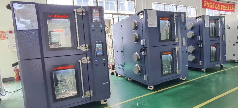
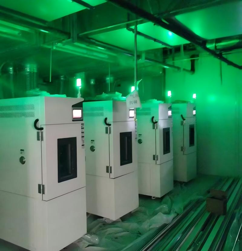
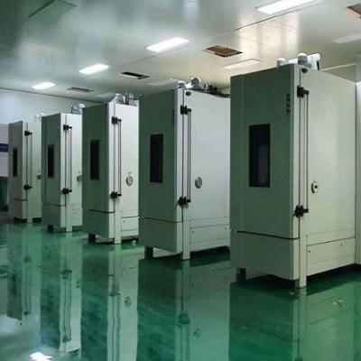
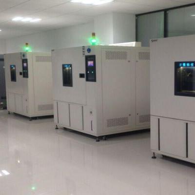
Définition et utilisation de la chambre d'essai de cyclage de températureChambre d'essai de cyclage de température est une sorte d'équipement de laboratoire largement utilisé dans diverses industries, sa fonction principale est de faire cycler le produit dans une certaine plage de température pour simuler le fonctionnement du produit dans différents environnements de température. L'équipement est un outil important pour réaliser des tests de fiabilité des produits, un contrôle qualité et une évaluation des performances des produits.La chambre d'essai de cyclage de température est largement utilisée et peut être utilisée pour des tests dans divers domaines, tels que l'aérospatiale, l'automobile, l'électronique, l'énergie électrique, le médical et d'autres domaines. Dans le secteur aérospatial, les chambres d'essais de cycles de température sont utilisées pour tester les performances des composants d'avions à des températures extrêmes afin de garantir leur fiabilité dans des environnements extrêmes. Dans le domaine automobile, la chambre d'essai du cycle de température est utilisée pour tester les performances des composants automobiles dans différentes conditions de température et d'humidité afin de garantir que la voiture peut fonctionner normalement dans divers environnements. Dans le domaine de l'électronique et de l'énergie, les chambres d'essai de cycles de température sont utilisées pour tester les performances et la fiabilité des équipements électroniques dans différentes conditions de température afin de garantir que l'équipement peut fonctionner de manière stable pendant une longue période. Dans le domaine médical, les chambres d'essai de cycles de température sont utilisées pour tester les performances et la fiabilité des équipements médicaux dans différentes conditions de température et d'humidité afin de garantir le fonctionnement normal de l'équipement.Le principe de fonctionnement de la chambre d'essai de cyclage de température consiste à effectuer l'essai de cyclage en contrôlant la température et l'humidité dans la chambre. L'appareil dispose d'une variété de modes de contrôle de la température, tels que le contrôle de la température constante, le contrôle de la température programmé, le contrôle de la température programmé, etc., qui peuvent être sélectionnés en fonction des besoins. Pendant le processus de test, la chambre de test de cycle de température placera le produit dans différents environnements de température pour le tester afin de simuler l'utilisation du produit dans différents environnements. Une fois le test terminé, les utilisateurs peuvent améliorer et mettre à niveau le produit en fonction des résultats du test afin d'améliorer la fiabilité et les performances du produit.En bref, la chambre d'essai de cyclage de température est un équipement de laboratoire largement utilisé dans diverses industries, et sa fonction principale est de faire cycler le produit dans une certaine plage de température pour simuler le fonctionnement du produit dans différents environnements de température. L'équipement peut être utilisé pour des tests dans divers domaines, tels que l'aérospatiale, l'automobile, l'électronique, l'énergie, le médical et d'autres domaines, et constitue un outil important pour réaliser des tests de fiabilité des produits, un contrôle qualité et une évaluation des performances des produits.
Principes que la chambre d'essai de température et d'humidité constantes de fonctionnement devrait suivre Chambre d'essai à température et humidité constantes, également connu sous le nom de machine d'essai de température et d'humidité constantes, chambre d'essai alternée de température et d'humidité programmables, thermostat ou chambre de température et d'humidité constantes, peut être utilisé pour tester divers environnements et tester les performances des matériaux de l'équipement, ce matériau a une résistance à la chaleur, une résistance au froid, sec résistance et résistance à l’humidité. Cependant, lors de l'utilisation de la chambre d'essai à température et humidité constantes, le bon fonctionnement permet d'obtenir des données scientifiques pour l'expérimentateur, alors quels principes doivent être suivis dans le fonctionnement de la chambre d'essai à température et humidité constantes ?u200eTout d'abord, lors de l'essai environnemental, l'opérateur doit être familier avec les performances requises de l'échantillon d'essai, les conditions d'essai, les procédures d'essai et la technologie d'essai, être familier avec les performances techniques de l'équipement d'essai utilisé et comprendre la structure de l'équipement, particulièrement familier avec le fonctionnement et les performances du contrôle. Dans le même temps, lisez attentivement le manuel d'utilisation de l'équipement de test pour éviter un fonctionnement anormal de l'équipement de test en raison d'erreurs de fonctionnement, ce qui pourrait endommager l'échantillon de test et des données de test incorrectes. u200eu200eDeuxièmement, afin de garantir le fonctionnement normal du test, un équipement de test approprié doit être sélectionné en fonction des différentes conditions de l'échantillon de test et d'une proportion raisonnable entre la température et l'humidité de l'échantillon de test et le volume efficace du laboratoire. devrait être maintenu. Pour les essais sur échantillons chauffés, le volume ne doit pas dépasser le dixième du volume effectif de la chambre d'essai. Le volume de l’échantillon d’essai non chauffé ne doit pas dépasser le cinquième du volume effectif de la chambre d’essai. u200eTroisièmement, pour les tests environnementaux qui nécessitent l'ajout de médias au test, ceux-ci doivent être correctement ajoutés conformément aux exigences du test. u200e Par exemple, il existe certaines exigences concernant l'eau dans les chambres d'essai de température et d'humidité et la résistance doit être réduite. Il existe une forme d’eau pure plus économique et plus pratique sur le marché. Sa résistance est équivalente à celle de l'eau distillée. u200eQuatrièmement, la gaze à bulbe humide (papier à bulbe humide) a certaines exigences pour une utilisation dans une chambre d'essai de température et d'humidité, et aucune gaze ne peut être remplacée, car la lecture de l'humidité relative est la différence entre la distance entre les racines et la température et l'humidité, et à proprement parler , elle est également liée à la pression atmosphérique locale et à la vitesse du vent du moment. La valeur indicatrice de la température du bulbe humide est liée à la quantité d’eau absorbée par la gaze et à la quantité d’évaporation superficielle. Celles-ci sont directement liées à la qualité de la gaze, c'est pourquoi la météo stipule que la gaze à boules humides doit être une « gaze à boules humides » spéciale tissée à partir de lin. Sinon, il est difficile de garantir l’exactitude de la valeur du thermomètre à bulbe humide, c’est-à-dire l’exactitude de l’humidité. De plus, la position de la gaze humide est également clairement indiquée. Longueur de la gaze : 100 mm, enveloppez étroitement la sonde du capteur, sonde à 25-30 mm de la coupelle d'humidité, gaze immergée dans la coupelle pour garantir la précision du contrôle de l'équipement et de l'humidité. u200eCinquièmement, l'emplacement de l'échantillon d'essai doit être à plus de 10 cm du mur de la chambre et plusieurs échantillons doivent être placés autant que possible sur le même plan. Les échantillons doivent être placés sans bloquer les sorties d’air ni les évents de retour, et les capteurs de température et d’humidité doivent être tenus à distance. Assurez-vous que la température de test est correcte. u200eEn faisant fonctionner la chambre d'essai à température et humidité constantes conformément aux principes ci-dessus, le bon fonctionnement du processus d'essai améliorera considérablement le niveau des données d'essai. Tant que les principes ci-dessus sont respectés, il faut dire que les tests de température et d’humidité peuvent être effectués avec succès. u200e
Machine de criblage de contrainte à changement de température rapide ESSDépistage du stress environnemental (ESS)Le dépistage des contraintes consiste à utiliser des techniques d'accélération et des contraintes environnementales inférieures à la limite de résistance de conception, telles que : brûlage, cycles de température, vibrations aléatoires, cycle d'alimentation... En accélérant la contrainte, les défauts potentiels du produit apparaissent [matériau potentiel des pièces défauts, défauts de conception, défauts de processus, défauts de processus], et éliminer les contraintes résiduelles électroniques ou mécaniques, ainsi que les condensateurs parasites entre les cartes de circuits imprimés multicouches, l'étape de mort précoce du produit dans la courbe du bain est supprimée et réparée à l'avance , de sorte que le produit passe par un contrôle modéré, économisez la période normale et la période de déclin de la courbe de la baignoire pour éviter le produit en cours d'utilisation, le test de stress environnemental conduit parfois à une défaillance, entraînant des pertes inutiles. Bien que l'utilisation du dépistage de stress ESS augmente le coût et le temps, pour améliorer le rendement de livraison du produit et réduire le nombre de réparations, il y a un effet significatif, mais le coût total sera réduit. En outre, la confiance des clients sera également améliorée, généralement pour les parties électroniques des méthodes de dépistage des contraintes sont la pré-combustion, le cycle de température, la haute température, la basse température, la méthode de dépistage des contraintes des circuits imprimés PCB est le cycle de température, pour le coût électronique du Le dépistage des contraintes est : la pré-combustion de l'alimentation, les cycles de température, les vibrations aléatoires, en plus du dépistage des contraintes lui-même est une étape du processus, plutôt qu'un test, le dépistage représente 100 % de la procédure du produit.Caractéristiques du produit de la machine de criblage de stress à changement rapide de température :1, il peut définir différentes variations de température de dépistage des contraintes de 5°C/min, 10°C/min et 15°C/min.2, il peut effectuer un changement rapide de température (dépistage des contraintes), un test de condensation, une température et une humidité élevées, un cycle de température et d'humidité et d'autres tests.3, il répond aux exigences du test de dépistage du stress des produits d'équipement électronique.4, il peut être commuté entre deux méthodes de test à température égale et à température moyenne.Exigences de spécification de la machine de criblage de contrainte à changement rapide de température :1, il peut définir une variété de conditions de test de dépistage des contraintes (variabilité rapide de la température) de 5 °C/min, 10 °C/min et 15 °C/min.2, il répond au dépistage du stress des produits d'équipement électronique, processus sans plomb, MIL-STD-2164, MIL-344A-4-16, MIL-2164A-19, NABMAT-9492, GJB-1032-90, GJB/Z34- 5.1.6, IPC-9701 et autres exigences de test.3, il peut effectuer un mode de test de température égale et de température moyenne.4, il utilise une feuille d'aluminium pour vérifier la capacité de charge de la machine (charge non plastique).
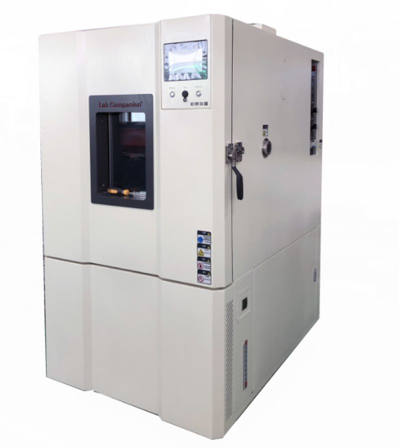
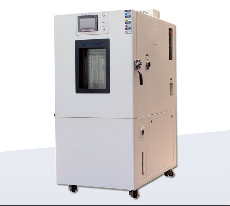
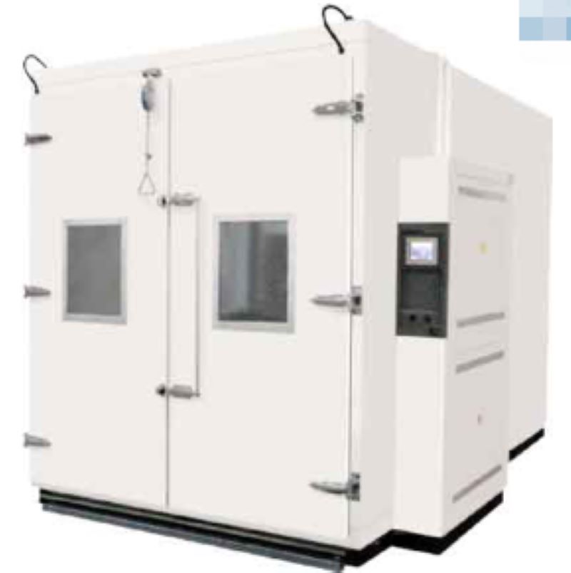
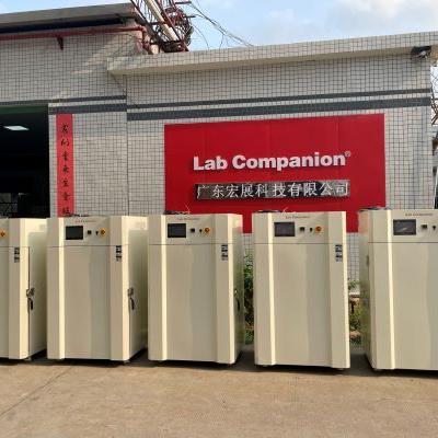
Chambre d'essai de cyclage rapide de la température Lab CompanionPrésentation de Lab CompanionAvec plus de 20 ans d'expérience, Compagnon de laboratoire est un fabricant de classe mondiale d'enceintes environnementales et un fournisseur accompli de systèmes et d'équipements de test clé en main. Toutes nos chambres s'appuient sur la réputation de Lab Companion en matière de longue durée de vie et de fiabilité exceptionnelle. Avec une portée de conception, de fabrication et de service, Lab Companion a établi un système de gestion de la qualité conforme à la norme internationale du système de qualité ISO 9001:2008. Le programme d'étalonnage des équipements de Lab Companion est accrédité selon la norme internationale ISO 17025 et la norme nationale américaine ANSI/NCSL-Z-540-1 par A2LA. A2LA est membre à part entière et signataire de la Coopération internationale pour l'accréditation des laboratoires (ILAC), de l'Asia Pacific Laboratory Accreditation (APLAC) et de la Coopération européenne pour l'accréditation (EA). Les chambres d'essais environnementaux de la série SE de Lab Companion offrent un système de circulation d'air considérablement amélioré, qui offre de meilleurs gradients et des taux de changement de température des produits améliorés. Ces chambres utilisent le programmeur/contrôleur phare 8800 de Thermotron, doté d'un écran plat haute résolution de 12,1 pouces avec interface utilisateur à écran tactile, de capacités étendues de création de graphiques, d'enregistrement de données, de modification, d'accès à l'aide à l'écran et de stockage de données sur disque dur à long terme.Non seulement nous proposons des produits de la plus haute qualité, mais nous fournissons également une assistance continue conçue pour vous permettre de rester opérationnel longtemps après la vente initiale. Nous fournissons un service local direct en usine avec un vaste inventaire des pièces dont vous pourriez avoir besoin. PerformancePlage de température : -70°C à +180°CPerformance : Avec une charge d'aluminium de 23 kg (IEC60068-3-5), le taux de montée de +85°C à -40°C est de 15℃/min ; la vitesse de refroidissement de -40°C à +85°C est également de 15℃/min.Contrôle de la température : ± 1°C Températures sèches à partir du point de contrôle après stabilisation au niveau du capteur de contrôleLes performances sont basées sur des conditions ambiantes de 75 °F (23,9 °C) et 50 % d'humidité relative.Performances de refroidissement/chauffage basées sur la mesure au niveau du capteur de contrôle dans le flux d'air souffléConstruireIntérieurAcier inoxydable non magnétique série 300 à haute teneur en nickelCoutures internes soudées à l'héliarc pour une fermeture hermétique du linerCoins et coutures conçus pour permettre l'expansion et la contraction sous les températures extrêmes rencontréesÉvacuation des condensats située dans le plancher liner et sous le plénum de climatisationLa base de la chambre est entièrement soudéeIsolant en fibre de verre « Ultra-Lite » non décantantUne tablette intérieure réglable en acier inoxydable est standardExtérieurTôle d'acier traitée matricéeCouvercles d'accès en métal fournis pour une ouverture facile des portes vers les composants électriquesVernis de finition à base d'eau, séché à l'air, pulvérisé sur une surface nettoyée et apprêtée.Portes d'accès à charnières faciles à soulever pour l'entretien du système de réfrigérationUn port d'accès de 12,5 cm de diamètre avec soudure intérieure et bouchon isolant amovible monté dans la paroi latérale droite, accessoires sur porte battante pour un accès facileCaractéristiquesLe fonctionnement de la chambre affiche clairement des informations utiles sur le temps d'exécutionL'écran graphique offre des capacités étendues, une programmation et des rapports améliorésL'état du système affiche les paramètres cruciaux du système de réfrigérationProgram Entry facilite le chargement, l'affichage et la modification des profilsLes assistants de configuration rapides facilitent la saisie du profilTableaux de réfrigération contextuels pour référence pratiqueTherm-Alarm® offre une protection par alarme de surchauffe et de sous-températureL'écran du journal d'activité fournit un historique complet de l'équipementLe serveur Web permet l'accès Internet aux équipements via EthernetLe clavier contextuel convivial rend la saisie des données rapide et facileComprend :- Quatre ports USB : deux externes et deux internes-Ethernet-RS-232Spécifications techniques1 à 4 canaux programmables indépendammentPrécision de mesure : 0,25 % de l'étendue typiqueÉchelle de température sélectionnable en °C ou °FÉcran tactile plat couleur de 12,1 pouces (30 cm)Résolution : 0,1°C, 0,1%RH, 0,01 pour d'autres applications linéairesHorloge en temps réel incluseTaux d'échantillonnage : variable de processus échantillonnée toutes les 0,1 secondeBande proportionnelle : programmable de 1,0 ° à 300 °Méthode de contrôle : numériqueIntervalles : illimitésRésolution d'intervalle : 1 seconde à 99 heures, 59 minutes avec une résolution de 1 seconde-RS-232- 10+ ans de stockage de données- Contrôle de la température du produit- Tableau de relais d'événementsModes de fonctionnement : automatique ou manuelStockage du programme : illimitéBoucles de programme :- Jusqu'à 64 boucles par programmeLes boucles peuvent être répétées jusqu'à 9 999 fois par programme- Jusqu'à 64 boucles imbriquées sont autorisées par
Test de stabilité du médicament
L'efficacité et la sécurité des médicaments ont attiré beaucoup d'attention, et il s'agit également d'une question de moyens de subsistance à laquelle le pays et le gouvernement attachent une grande importance. La stabilité des médicaments affectera leur efficacité et leur sécurité. Afin de garantir la qualité des médicaments et des conteneurs de stockage, des tests de stabilité doivent être effectués pour déterminer leur durée d'efficacité et leur état de stockage. Le test de stabilité étudie principalement si la qualité des médicaments est affectée par des facteurs environnementaux tels que la température, l'humidité et la lumière, et si elle change avec le temps et la corrélation entre eux, et étudie la courbe de dégradation des médicaments, selon laquelle la période d'efficacité est présumée pour garantir l’efficacité et la sécurité des médicaments lorsqu’ils sont utilisés. Cet article rassemble les informations standard et les méthodes de test requises pour divers tests de stabilité pour référence des clients.
Premièrement, les critères des tests de stabilité des médicaments
Conditions de conservation des médicaments :
Conditions de stockage (Remarque 2)
Expérience à long terme
25℃±2℃ / 60 %±5 % HR ou
30 ℃ ± 2 ℃ /65 % ± 5 % d'humidité relative
Test accéléré
40 ℃ ± 2 ℃ / 75 % ± 5 % HR
Test intermédiaire (Remarque 1)
30 ℃ ± 2 ℃ / 65 % ± 5 % HR
Remarque 1 : Si la condition de test à long terme a été réglée à 30 ℃ ± 2 ℃/65 % ± 5 % HR, il n'y a pas de test intermédiaire ; si les conditions de stockage à long terme sont de 25 ℃ ± 2 ℃/60 % ± 5 % HR et qu'il y a un changement significatif dans le test accéléré, alors un test intermédiaire doit être ajouté. Et devrait être évalué selon le critère de « changement significatif ».
Remarque 2 : Les récipients imperméables scellés tels que les ampoules en verre peuvent être exemptés des conditions d'humidité. Sauf indication contraire, tous les tests doivent être effectués conformément au plan de test de stabilité lors de l'essai intermédiaire.
Les données des tests accélérés devraient être disponibles pendant six mois. La durée minimale du test de stabilité est de 12 mois pour le test moyen et le test longue durée.
Conserver au réfrigérateur :
Conditions de stockage
Expérience à long terme
5 ℃ ± 3 ℃
Test accéléré
25 ℃ ± 2 ℃ / 60 % ± 5 % HR
Conservé au congélateur :
Conditions de stockage
Expérience à long terme
-20 ℃ ± 5 ℃
Test accéléré
5 ℃ ± 3 ℃
Si le produit contenant de l'eau ou des solvants susceptibles de perdre du solvant est conditionné dans un récipient semi-perméable, l'évaluation de la stabilité doit être effectuée sous une faible humidité relative pendant une longue période, ou un test intermédiaire de 12 mois, et un test accéléré de 6 mois, afin de prouver que le médicament placé dans le récipient semi-perméable peut résister à un environnement à faible humidité relative.
Contenant de l'eau ou des solvants
Conditions de stockage
Expérience à long terme
25 ℃ ± 2 ℃ / 40 % ± 5 % RH ou 30 ℃ ± 2 ℃ /35 % ± 5 % d'humidité relative
Test accéléré
40 ℃ ± 2 ℃ ; ≤ 25 % HR
Test intermédiaire (Remarque 1)
30 ℃ ± 2 ℃ / 35 % HR ± 5 % HR
Remarque 1 : Si la condition de test à long terme est de 30 ℃ ± 2 ℃ / 35 % ± 5 % HR, il n'y a pas de test intermédiaire.
Le calcul du taux de perte relative d’eau à une température constante de 40℃ est le suivant :
Humidité relative substituée (A)
Contrôler l'humidité relative (R)
Rapport du taux de perte d'eau ([1-R]/[1-A])
60% HR
25% HR
1.9
60% HR
40% HR
1,5
65% HR
35% HR
1.9
75% HR
25% HR
3.0
Illustration : Pour les médicaments aqueux placés dans des récipients semi-perméables, le taux de perte d'eau à 25%HR est trois fois supérieur à 75%HR.
Deuxièmement, les solutions de stabilité des médicaments
Critères courants des tests de stabilité des médicaments
(Source : Food and Drug Administration, ministère de la Santé et du Bien-être social)
Article
Conditions de stockage
Expérience à long terme
25°C /60% HR
Test accéléré
40°C /75%HR
Test intermédiaire
30°C/65%HR
(1) Test sur une large plage de température
Article
Conditions de stockage
Expérience à long terme
Conditions de température basse ou inférieure à zéro
Test accéléré
Température et humidité ambiantes ou conditions de basse température
(2) Équipement d'essai
1. Chambre d'essai à température et humidité constantes
2. Chambre de test de stabilité des médicaments
Conditions de test des ordinateurs portablesL'ordinateur portable depuis le début de l'évolution de l'écran de 12 pouces jusqu'à l'écran rétroéclairé par LED actuel, son efficacité informatique et son traitement 3D, ne seront pas perdus au profit de l'ordinateur de bureau général, et le poids devient de moins en moins lourd, les exigences relatives des tests de fiabilité pour l'ensemble de l'ordinateur portable devient de plus en plus strict, depuis le premier emballage jusqu'au démarrage actuel, en passant par les températures et humidités élevées traditionnelles jusqu'au test de condensation actuel. De la plage de température et d'humidité de l'environnement général au test du désert en tant que condition courante, ce sont les éléments qui doivent être pris en compte dans la production de composants et de conception liés aux ordinateurs portables, les conditions de test des tests environnementaux pertinents collectés jusqu'à présent. sont organisés et partagés avec vous.Test de frappe du clavier :Testez-en un :Go : 1 million de foisPression clé : 0,3 ~ 0,8 (N)Course du bouton : 0,3 ~ 1,5 (mm)Test 2 : Pression des touches : 75 g (± 10 g) Testez 10 touches pendant 14 jours, 240 fois par minute, un total d'environ 4,83 millions de fois, une fois tous les 1 million de fois.Fabricants japonais : 2 à 5 millions de foisFabricant taïwanais 1 : plus de 8 millions de foisFabricant taïwanais 2 : 10 millions de foisTest de traction de l'interrupteur d'alimentation et de la fiche du connecteur :Ce modèle de test simule les forces latérales auxquelles chaque connecteur peut résister en cas d'utilisation anormale. Éléments de test généraux pour ordinateurs portables : USB, 1394, PS2, RJ45, Modem, VGA... Force d'application égale 5 kg (50 fois), tirez et branchez de haut en bas à gauche et à droite.Test de l'interrupteur d'alimentation et de la fiche du connecteur :4000 fois (alimentation)Test d'ouverture et de fermeture du cache écran :Fabricants taïwanais : ouvrent et ferment 20 000 foisFabricant japonais 1 : test d'ouverture et de fermeture 85 000 foisFabricant japonais 2 : ouverture et fermeture 30 000 foisTest du commutateur de veille et de récupération du système :Type de note générale : intervalle de 10 sec, 1000 cyclesFabricant japonais : test du commutateur de veille et de récupération du système 2 000 foisCauses courantes de panne d'un ordinateur portable :☆ Des objets étrangers tombent sur le carnet☆ Tombe de la table pendant l'utilisation☆ Rangez le carnet dans un sac à main ou une valise à roulettes☆ Température extrêmement élevée ou basse température ☆ Utilisation normale (surutilisation)☆ Mauvaise utilisation dans les destinations touristiques☆PCMCIA mal inséré☆ Placez des objets étrangers sur le clavierTest de chute d'arrêt :Type de carnet général :76 cmChute du colis GB : 100 cmOrdinateurs portables de l'armée américaine et japonais : la hauteur de l'ordinateur est de 90 cm de tous les côtés, côtés, coins, un total de 26 côtés.Plateforme :74 cm (emballage requis)Terrain : 90cm (emballage requis)TOSHIBA&BENQ 100 cmTest de chute de démarrage :Japonais : Chute de botte de 10 cmTaïwan :Chute de botte de 74 cmChoc thermique de la carte principale de l'ordinateur portable :Pente 20℃/minNombre de cycles 50cycles (aucune opération pendant l'impact)Les normes techniques et conditions de test de l'armée américaine pour l'achat d'ordinateurs portables sont les suivantes :Test d'impact : Faites tomber l'ordinateur 26 fois de tous les côtés, côtés et coins à une hauteur de 90 cmTest de résistance aux tremblements de terre : 20 Hz ~ 1 000 Hz, fréquence 1 000 Hz ~ 2 000 Hz une fois par heure, vibration continue des axes X, Y et ZTest de température : 0 ℃ ~ 60 ℃ 72 heures de vieillissement au fourTest d'étanchéité : vaporisez de l'eau sur l'ordinateur pendant 10 minutes dans toutes les directions, et le débit de pulvérisation d'eau est de 1 mm par minute.Test de poussière : Pulvériser la concentration de 60 000 mg/par mètre cube de poussière pendant 2 secondes (intervalle de 10 minutes, 10 fois consécutives, durée 1 heure)Conforme aux spécifications militaires MIL-STD-810Test d'étanchéité :Ordinateur portable de l'armée américaine :classe de protection :IP54 (poussière et pluie) J'ai aspergé l'ordinateur d'eau dans toutes les directions pendant 10 minutes à raison de 1 mm par minute.Test anti-poussière :Carnet de l'armée américaine : Pulvériser une concentration de 60 000 mg/m3 de poussière pendant 2 secondes (intervalles de 10 minutes, 10 fois consécutives, durée 1 heure)
Conditions de température et d'humiditéLa température du point de rosée Td, dans la teneur en vapeur d'eau de l'air inchangée, maintient une certaine pression, de sorte que le refroidissement de l'air atteigne la température de saturation appelée température du point de rosée, appelée point de rosée, l'unité est exprimée en ° C ou ℉. C'est en fait la température à laquelle la vapeur d'eau et l'eau sont en équilibre. La différence entre la température réelle (t) et la température du point de rosée (Td) indique le degré de saturation de l'air. Lorsque t>Td, cela signifie que l'air n'est pas saturé, lorsque t=Td, il est saturé, et lorsque t
Zone de conduction de la chaleurConductivité thermiqueC'est la conductivité thermique d'une substance, passant d'une température élevée à une température basse au sein de cette même substance. Également connu sous le nom de : conductivité thermique, conductivité thermique, conductivité thermique, coefficient de transfert thermique, transfert de chaleur, conductivité thermique, conductivité thermique, conductivité thermique, conductivité thermique.Formule de conductivité thermiquek = (Q/t) *L/(A*T) k : conductivité thermique, Q : chaleur, t : temps, L : longueur, A : surface, T : différence de température en unités SI, l'unité de conductivité thermique est W/(m*K), en unités impériales, correspond à Btu · pi/(h · pi2 · °F)Coefficient de transfert de chaleurEn thermodynamique, en génie mécanique et en génie chimique, la conductivité thermique est utilisée pour calculer la conduction thermique, principalement la conduction thermique de convection ou la transformation de phase entre fluide et solide, qui est définie comme la chaleur traversant l'unité de surface par unité de temps sous la différence de température unitaire, appelée coefficient de conduction thermique de la substance, si l'épaisseur de la masse de L, la valeur de mesure doit être multipliée par L, La valeur résultante est le coefficient de conductivité thermique, généralement noté k.Conversion unitaire du coefficient de conduction thermique1 (CAL) = 4,186 (j), 1 (CAL/s) = 4,186 (j/s) = 4,186 (W).L'impact de la température élevée sur les produits électroniques :L'augmentation de la température entraînera une diminution de la valeur de résistance de la résistance, mais réduira également la durée de vie du condensateur. De plus, la température élevée entraînera une diminution du transformateur, des performances des matériaux d'isolation associés et une température trop élevée. un niveau élevé entraînera également une modification de la structure de l'alliage du joint de soudure sur la carte PCB : l'IMC s'épaissit, les joints de soudure deviennent cassants, les moustaches d'étain augmentent, la résistance mécanique diminue, la température de jonction augmente, le rapport d'amplification du courant du transistor augmente rapidement, ce qui entraîne une augmentation du courant du collecteur. , la température de jonction augmente encore et enfin la défaillance des composants.Explication des termes appropriés :Température de jonction : température réelle d'un semi-conducteur dans un appareil électronique. En fonctionnement, elle est généralement supérieure à la température du boîtier de l'emballage et la différence de température est égale au flux de chaleur multiplié par la résistance thermique. Convection libre (convection naturelle) : Rayonnement (rayonnement) : Air forcé (refroidissement du gaz) : Liquide forcé (refroidissement du gaz) : Liquide Évaporation : Surface Environnement EnvironnementConsidérations simples courantes pour la conception thermique :1 Des méthodes de refroidissement simples et fiables telles que la conduction thermique, la convection naturelle et le rayonnement doivent être utilisées pour réduire les coûts et les pannes.2 Raccourcissez autant que possible le chemin de transfert de chaleur et augmentez la zone d'échange thermique.3 Lors de l'installation des composants, l'influence de l'échange thermique par rayonnement des composants périphériques doit être pleinement prise en compte, et les dispositifs thermosensibles doivent être tenus à l'écart de la source de chaleur ou trouver un moyen d'utiliser les mesures de protection de l'écran thermique pour isoler les composants de la source de chaleur.4 Il doit y avoir une distance suffisante entre l'entrée d'air et l'orifice d'échappement pour éviter le reflux d'air chaud.5 La différence de température entre l'air entrant et l'air sortant doit être inférieure à 14°C.6 Il convient de noter que la direction de la ventilation forcée et de la ventilation naturelle doit être autant que possible cohérente.7 Les appareils à forte chaleur doivent être installés aussi près que possible de la surface qui est facile à dissiper la chaleur (telle que la surface intérieure du boîtier métallique, la base métallique et le support métallique, etc.), et il y a une bonne conduction thermique de contact entre la surface.8 La partie alimentation du tube haute puissance et la pile du pont redresseur appartiennent au dispositif de chauffage, il est préférable de l'installer directement sur le boîtier pour augmenter la zone de dissipation thermique. Dans la disposition de la carte imprimée, davantage de couches de cuivre doivent être laissées sur la surface de la carte autour du plus grand transistor de puissance pour améliorer la capacité de dissipation thermique de la plaque inférieure.9 Lorsque vous utilisez la convection libre, évitez d'utiliser des dissipateurs thermiques trop denses.10 La conception thermique doit être prise en compte pour garantir que la capacité de transport de courant du fil et le diamètre du fil sélectionné doivent être adaptés à la conduction du courant, sans provoquer une augmentation de température et une chute de pression supérieures à celles autorisées.11 Si la répartition de la chaleur est uniforme, l'espacement des composants doit être uniforme pour que le vent circule uniformément à travers chaque source de chaleur.12 Lorsque vous utilisez un refroidissement par convection forcée (ventilateurs), placez les composants sensibles à la température le plus près de l'entrée d'air.13 L'utilisation d'un équipement de refroidissement par convection libre pour éviter de disposer d'autres pièces au-dessus des pièces à forte consommation d'énergie, l'approche correcte doit être une disposition horizontale inégale.14 Si la répartition de la chaleur n'est pas uniforme, les composants doivent être disposés de manière clairsemée dans la zone à forte génération de chaleur, et la disposition des composants dans la zone à faible génération de chaleur doit être légèrement plus dense, ou ajouter une barre de dérivation, de sorte que l'énergie éolienne peut circuler efficacement vers les principaux appareils de chauffage.15 Le principe de conception structurelle de l'entrée d'air : d'une part, essayer de minimiser sa résistance au flux d'air, d'autre part, considérer la prévention de la poussière et considérer globalement l'impact des deux.16 Les composants de consommation électrique doivent être espacés autant que possible.17 Évitez de regrouper les pièces sensibles à la température ou de les disposer à côté de pièces à forte consommation d'énergie ou de points chauds.18 L'utilisation d'un équipement de refroidissement par convection libre pour éviter de disposer d'autres pièces au-dessus des pièces à forte consommation d'énergie, la pratique correcte doit être une disposition horizontale inégale.
Dépistage des contraintes cycliques de température (1)Dépistage du stress environnemental (ESS)Le dépistage des contraintes consiste à utiliser des techniques d'accélération et des contraintes environnementales inférieures à la limite de résistance de conception, telles que : brûlage, cycles de température, vibrations aléatoires, cycle d'alimentation... En accélérant la contrainte, les défauts potentiels du produit apparaissent [matériau potentiel des pièces défauts, défauts de conception, défauts de processus, défauts de processus], et éliminer les contraintes résiduelles électroniques ou mécaniques, ainsi que les condensateurs parasites entre les cartes de circuits imprimés multicouches, l'étape de mort précoce du produit dans la courbe du bain est supprimée et réparée à l'avance , de sorte que le produit grâce à un dépistage modéré, enregistre la période normale et la période de déclin de la courbe de la baignoire pour éviter le produit en cours d'utilisation, le test de stress environnemental conduit parfois à une défaillance, entraînant des pertes inutiles. Bien que l'utilisation du dépistage de stress ESS augmente le coût et le temps, pour améliorer le rendement de livraison du produit et réduire le nombre de réparations, il y a un effet significatif, mais le coût total sera réduit. En outre, la confiance des clients sera également améliorée, généralement pour les parties électroniques des méthodes de dépistage des contraintes sont la pré-combustion, le cycle de température, la haute température, la basse température, la méthode de dépistage des contraintes des circuits imprimés PCB est le cycle de température, pour le coût électronique du Le dépistage des contraintes est : la pré-combustion de l'alimentation, les cycles de température, les vibrations aléatoires, en plus du dépistage des contraintes lui-même est une étape du processus, plutôt qu'un test, le dépistage représente 100 % de la procédure du produit.Étape du produit applicable à l'évaluation des contraintes: Étape de R&D, étape de production de masse, avant la livraison (le test de dépistage peut être effectué sur les composants, les dispositifs, les connecteurs et autres produits ou sur l'ensemble du système de machine, selon différentes exigences, il peut avoir différentes contraintes de dépistage)Comparaison du dépistage du stress :un. Le dépistage des contraintes de pré-combustion (Burn in) à haute température constante est la méthode couramment utilisée par l'industrie informatique électronique actuelle pour précipiter les défauts des composants électroniques, mais cette méthode ne convient pas au dépistage des pièces (PCB, IC, résistance, condensateur), selon les statistiques. , le nombre d'entreprises aux États-Unis qui utilisent des cycles de température pour filtrer les pièces est cinq fois plus élevé que le nombre d'entreprises qui utilisent une précuisson constante à haute température pour filtrer les composants.B. GJB/DZ34 indique la proportion de défauts de sélection du cycle de température et du tamis vibrant aléatoire, la température représentait environ 80 %, les vibrations représentaient environ 20 % des défauts de divers produits.c. Les États-Unis ont mené une enquête auprès de 42 entreprises. Les contraintes vibratoires aléatoires peuvent éliminer 15 à 25 % des défauts, tandis que le cycle de température peut en éliminer 75 à 85 %, si la combinaison des deux peut atteindre 90 %.d. La proportion de types de défauts de produits détectés par les cycles de température : marge de conception insuffisante : 5 %, erreurs de production et de fabrication : 33 %, pièces défectueuses : 62 %Description de l'induction de défauts du dépistage des contraintes cycliques en température :La cause de la défaillance du produit induite par les cycles de température est la suivante : lorsque la température varie entre les températures extrêmes supérieure et inférieure, le produit produit une expansion et une contraction alternées, entraînant une contrainte et une déformation thermiques dans le produit. S'il existe une échelle thermique transitoire (non-uniformité de la température) à l'intérieur du produit, ou si les coefficients de dilatation thermique des matériaux adjacents à l'intérieur du produit ne correspondent pas, ces contraintes et déformations thermiques seront plus drastiques. Ces contraintes et déformations sont plus importantes au niveau du défaut, et ce cycle fait que le défaut devient si important qu'il peut éventuellement provoquer une défaillance structurelle et générer une panne électrique. Par exemple, un trou traversant fissuré par galvanoplastie finit par se fissurer complètement autour de lui, provoquant un circuit ouvert. Le cycle thermique permet le soudage et le placage à travers les trous des cartes de circuits imprimés... Le dépistage des contraintes cycliques en température est particulièrement adapté aux produits électroniques dotés d'une structure de circuit imprimé.Le mode défaut déclenché par le cycle de température ou l'impact sur le produit est le suivant :un. L'expansion de diverses fissures microscopiques dans le revêtement, le matériau ou le filb. Desserrer les joints mal collésc. Desserrer les joints mal connectés ou rivetésd. Détendez les raccords pressés avec une tension mécanique insuffisantee. Augmente la résistance de contact des joints de soudure de mauvaise qualité ou provoque un circuit ouvertf. Particules, pollution chimiqueg. Défaillance du jointh. Problèmes d'emballage, tels que le collage des revêtements protecteursje. Court-circuit ou circuit ouvert du transformateur et de la bobinej. Le potentiomètre est défectueuxk. Mauvaise connexion des points de soudure et de soudurel. Contact de soudage à froidm. Carte multicouche due à une mauvaise manipulation d'un circuit ouvert, d'un court-circuitn. Court-circuit du transistor de puissanceo. Condensateur, transistor défectueuxp. Défaillance du circuit intégré à double rangéeq. Un boîtier ou un câble qui est presque en court-circuit en raison de dommages ou d'un assemblage incorrectr. Casse, casse, éraflure du matériel dû à une mauvaise manipulation... Etc.s. pièces et matériaux hors tolérancest. résistance rompue en raison du manque de revêtement tampon en caoutchouc synthétiquetoi. Les poils du transistor participent à la mise à la terre de la bande métalliquev. Rupture du joint d'isolation en mica, entraînant un court-circuit du transistorw. Une mauvaise fixation de la plaque métallique de la bobine de régulation entraîne un débit irrégulierX. Le tube à vide bipolaire est ouvert intérieurement à basse températurey. Court-circuit indirect de la bobinez. Bornes non mises à la terrea1. Dérive des paramètres du composanta2. Les composants sont mal installésa3. Composants mal utilisésa4. Défaillance du jointIntroduction de paramètres de contrainte pour le dépistage des contraintes cycliques en température :Les paramètres de contrainte du dépistage des contraintes cycliques de température comprennent principalement les éléments suivants : plage extrême de températures élevées et basses, temps de séjour, variabilité de la température, numéro de cycle.Plage extrême de haute et basse température: plus la plage de température extrême haute et basse est grande, moins de cycles sont nécessaires, plus le coût est faible, mais ne peut pas dépasser la limite du produit, ne provoque pas de nouveau principe de défaut, la différence entre le Les limites supérieure et inférieure du changement de température ne sont pas inférieures à 88 °C, la plage de changement typique est de -54 °C à 55 °C.Temps de séjour : De plus, le temps de séjour ne peut pas être trop court, sinon il est trop tard pour que le produit testé produise des changements de contrainte de dilatation thermique et de contraction, comme pour le temps de séjour, le temps de séjour des différents produits est différent, vous peut se référer aux exigences des spécifications pertinentes.Nombre de cycles : Quant au nombre de cycles de dépistage des contraintes cycliques en température, il est également déterminé en tenant compte des caractéristiques du produit, de la complexité, des limites supérieures et inférieures de température et du taux de dépistage, et le nombre de dépistage ne doit pas être dépassé, sinon cela entraînerait nuire inutilement au produit et ne peut pas améliorer le taux de dépistage. Le nombre de cycles de température varie de 1 à 10 cycles [criblage ordinaire, criblage primaire] à 20 à 60 cycles [criblage de précision, criblage secondaire], pour l'élimination des défauts de fabrication les plus probables, environ 6 à 10 cycles peuvent être efficacement éliminés , en plus de l'efficacité du cycle de température, dépend principalement de la variation de température de la surface du produit, plutôt que de la variation de température à l'intérieur de la boîte de test.Il existe sept principaux paramètres influençant le cycle de température :(1) Plage de température(2) Nombre de cycles(3) Taux de température de Chang(4) Temps de séjour(5) Vitesses du flux d'air(6) Uniformité de la contrainte(7) Test de fonctionnement ou non (Condition de fonctionnement du produit)
AEC-Q100 - Mécanisme de défaillance basé sur la certification des tests de résistance des circuits intégrésAvec les progrès de la technologie électronique automobile, il existe de nombreux systèmes de contrôle de gestion de données complexes dans les voitures d'aujourd'hui, et via de nombreux circuits indépendants, pour transmettre les signaux requis entre chaque module, le système à l'intérieur de la voiture ressemble à « l'architecture maître-esclave » de le réseau informatique, dans l'unité de commande principale et chaque module périphérique, les pièces électroniques automobiles sont divisées en trois catégories. Y compris les circuits intégrés, les semi-conducteurs discrets et les composants passifs, trois catégories, afin de garantir que ces composants électroniques automobiles répondent aux normes les plus élevées de l'anquan automobile, l'American Automotive Electronics Association (AEC, The Automotive Electronics Council est un ensemble de normes [AEC-Q100] conçu pour les pièces actives [microcontrôleurs et circuits intégrés...] et [[AEC-Q200] conçu pour les composants passifs, qui spécifie la qualité et la fiabilité du produit qui doivent être atteintes pour les pièces passives. Aec-q100 est la norme de test de fiabilité des véhicules formulée. par l'organisation AEC, qui constitue une entrée importante pour les fabricants de 3C et de circuits intégrés dans le module d'usine automobile internationale, et également une technologie importante pour améliorer la qualité de fiabilité des circuits intégrés de Taiwan. De plus, l'usine automobile internationale a passé la norme anquan (ISO). -26262). AEC-Q100 est l’exigence de base pour réussir cette norme.Liste des pièces électroniques automobiles requises pour passer l'AECQ-100 :Mémoire jetable automobile, régulateur abaisseur d'alimentation, photocoupleur automobile, capteur accéléromètre à trois axes, dispositif vidéo Jiema, redresseur, capteur de lumière ambiante, mémoire ferroélectrique non volatile, circuit intégré de gestion de l'alimentation, mémoire flash intégrée, régulateur DC/DC, véhicule dispositif de communication réseau de jauge, circuit intégré de pilote LCD, amplificateur différentiel d'alimentation unique, interrupteur de proximité capacitif désactivé, pilote de LED haute luminosité, commutateur asynchrone, circuit intégré 600 V, circuit intégré GPS, puce de système avancé d'aide à la conduite ADAS, récepteur GNSS, amplificateur frontal GNSS. .. Attendons.Catégories et tests AEC-Q100 :Description : Spécification AEC-Q100 7 grandes catégories, un total de 41 testsGroupe A- TESTS DE STRESS ENVIRONNEMENT ACCÉLÉRÉS se compose de 6 tests : PC, THB, HAST, AC, UHST, TH, TC, PTC, HTSLGroupe B - TESTS DE SIMULATION ACCÉLÉRÉS À VIE se compose de trois tests : HTOL, ELFR et EDRLES TESTS D'INTÉGRITÉ DE L'ASSEMBLAGE DU COLIS se composent de 6 tests : WBS, WBP, SD, PD, SBS, LIGroupe D- Le test de FIABILITÉ DE FABRICATION DES MATRICES se compose de 5 TESTS : EM, TDDB, HCI, NBTI, SMLe groupe TESTS DE VÉRIFICATION ÉLECTRIQUE se compose de 11 tests, dont TEST, FG, HBM/MM, CDM, LU, ED, CHAR, GL, EMC, SC et SER.TESTS DE DÉPISTAGE des défauts F du cluster : 11 tests, dont : PAT, SBALes TESTS D'INTÉGRITÉ DU PACKAGE CAVITY se composent de 8 tests, dont : MS, VFV, CA, GFL, DROP, LT, DS, IWV.Brève description des éléments de test :Climatisation : AutocuiseurCA : accélération constanteCDM : mode appareil chargé par décharge électrostatiqueCHAR : indique la description de la fonctionnalitéDROP : le colis tombeDS : test de cisaillement des copeauxED : Distribution électriqueEDR : durabilité du stockage non sujette aux pannes, conservation des données, durée de vieELFR : taux d’échec en début de vieEM : électromigrationCEM : Compatibilité électromagnétiqueFG : niveau de défautGFL : test de fuite d'air grossier/finGL : Fuite de grille causée par un effet thermoélectriqueHBM : indique le mode humain de décharge électrostatiqueHTSL : durée de conservation à haute températureHTOL : durée de vie à haute températureHCL : effet d'injection de porteur chaudIWV : Test hygroscopique interneLI : intégrité des brochesLT : Test de couple du couvercleLU : effet de verrouillageMM : indique le mode mécanique de décharge électrostatiqueMS : Choc mécaniqueNBTI : instabilité de température à biais richePAT : test de moyenne de processusPC : prétraitementPD : taille physiquePTC : cycle de température de puissanceSBA : Analyse statistique du rendementSBS : cisaillement de billes d'étainSC : fonction de court-circuitSD : soudabilitéSER : taux d'erreur logicielSM : Migration des contraintesTC : cycle de températureTDDB : Temps de claquage diélectriqueTEST : Paramètres de fonction avant et après stress testTH : humidité et chaleur sans parti prisTHB, HAST : tests de température, d'humidité ou de stress hautement accélérés avec biais appliquésUHST : test de résistance à haute accélération sans biaisVFV : vibration aléatoireWBS : coupe au fil de soudureWBP : tension du fil de soudureConditions de test de température et d'humidité finition :THB (température et humidité avec polarisation appliquée, selon JESD22 A101) : 85℃/85%R.H./1000h/biasHAST (test de contrainte hautement accéléré selon JESD22 A110) : 130℃/85%R.H./96h/bias, 110℃/85%R.H./264h/biasAutocuiseur AC, selon JEDS22-A102 : 121 ℃/100%R.H./96hUHST Test de contrainte à haute accélération sans biais, selon JEDS22-A118, équipement : HAST-S) : 110℃/85%R.H./264hTH chaleur humide sans biais, selon JEDS22-A101, équipement : THS) : 85℃/85%R.H./1000hTC(cycle de température, selon JEDS22-A104, équipement : TSK, TC) :Niveau 0 : -50℃←→150℃/2000cyclesNiveau 1 : -50℃←→150℃/1000cyclesNiveau 2 : -50℃←→150℃/500cyclesNiveau 3 : -50℃←→125℃/500cyclesNiveau 4 : -10℃←→105℃/500cyclesPTC (cycle de température de puissance, selon JEDS22-A105, équipement : TSK) :Niveau 0 : -40℃←→150℃/1000cyclesNiveau 1 : -65℃←→125℃/1000cyclesNiveau 2 à 4 : -65℃←→105℃/500cyclesHTSL(Durée de conservation haute température, JEDS22-A103, appareil : FOUR) :Pièces d'emballage en plastique : Grade 0 : 150 ℃/2000hCatégorie 1 : 150 ℃/1000hGrade 2 à 4 : 125 ℃/1000h ou 150℃/5000hPièces d'emballage en céramique : 200 ℃/72hHTOL (Durée de vie haute température, JEDS22-A108, équipement : FOUR) :Catégorie 0 : 150 ℃/1000hClasse 1 : 150℃/408h ou 125℃/1000hNiveau 2 : 125 ℃/408h ou 105 ℃/1000hNiveau 3 : 105 ℃/408h ou 85 ℃/1000hClasse 4 :90℃/408h ou 70℃/1000h ELFR (taux d'échec en début de vie, AEC-Q100-008) : Les appareils qui réussissent ce test de résistance peuvent être utilisés pour d'autres tests de résistance, les données générales peuvent être utilisées et les tests avant et après ELFR sont effectués dans des conditions de température douces et élevées.
Test de rupture transitoire du cycle de température de la plaque VMR
Le test de cycle de température est l'une des méthodes les plus couramment utilisées pour tester la fiabilité et la durée de vie des matériaux de soudage sans plomb et des pièces CMS. Il évalue les pièces adhésives et les joints de soudure sur la surface des CMS et provoque une déformation plastique et une fatigue mécanique des matériaux des joints de soudure sous l'effet de fatigue du cycle de température froide et chaude avec une variabilité de température contrôlée, afin de comprendre les dangers potentiels et les facteurs de défaillance. de joints de soudure et CMS. Le diagramme en guirlande est connecté entre les pièces et les joints de soudure. Le processus de test détecte les coupures et les coupures entre les lignes, les pièces et les joints de soudure grâce au système de mesure de rupture instantanée à grande vitesse, qui répond à la demande de test de fiabilité des connexions électriques pour évaluer si les joints de soudure, les billes d'étain et les pièces tombent en panne. Ce test n'est pas vraiment simulé. Son objectif est d'appliquer des contraintes sévères et d'accélérer le facteur de vieillissement sur l'objet à tester pour confirmer si le produit est conçu ou fabriqué correctement, puis d'évaluer la durée de vie en fatigue thermique des joints de soudure des composants. Le test de fiabilité de la connexion électrique à coupure instantanée à grande vitesse est devenu un maillon clé pour assurer le fonctionnement normal du système électronique et éviter la défaillance de la connexion électrique causée par la défaillance du système immature. Les changements de résistance sur une courte période de temps ont été observés lors de changements accélérés de température et d’essais de vibration.
But:
1. S'assurer que les produits conçus, fabriqués et assemblés répondent aux exigences prédéterminées
2. Relaxation de la contrainte de fluage des joints de soudure et de la rupture de rupture CMS causée par la différence de dilatation thermique
3. La température maximale de test du cycle de température doit être inférieure de 25 ℃ à la température Tg du matériau PCB, afin d'éviter plus d'un mécanisme d'endommagement du produit de test de remplacement.
4. La variabilité de la température à 20 ℃/min est un cycle de température, et la variabilité de la température au-dessus de 20 ℃/min est un choc thermique.
5. L'intervalle de mesure dynamique du joint de soudage ne dépasse pas 1 min
6. Le temps de séjour à haute et basse température pour la détermination des défaillances doit être mesuré en 5 coups.
Exigences:
1. Le temps de température total du produit testé se situe dans la plage de la température maximale nominale et de la température minimale, et la durée du temps de séjour est très importante pour le test accéléré, car le temps de séjour n'est pas suffisant pendant le test accéléré. , ce qui rendra le processus de fluage incomplet
2. La température du résident doit être supérieure à la température Tmax et inférieure à la température Tmin.
Se référer à la liste des spécifications :
IPC-9701, IPC650-2.6.26, IPC-SM-785, IPCD-279, J-STD-001, J-STD-002, J-STD-003, JESD22-A104, JESD22-B111, JESD22-B113, JESD22-B117 , SJR-01


 Obtenez un devis
 Réseau IPv6 pris en charge