Polypropylene (PP) itself is a highly flammable hydrocarbon with a limiting oxygen index (LOI) of only 17.8%. It will continue to burn even after being removed from the fire source. The core principle of flame-retardant PP is to interrupt or delay its combustion cycle through physical and chemical means. Combustion requires the simultaneous existence of three elements: combustible material, heat and oxygen. The function of flame retardants is to destroy this "burning triangle".
In industry, flame retardancy is mainly achieved by adding flame retardants to PP. Different types of flame retardants function through the following mechanisms:
1. Gas-phase flame retardant mechanism
This is one of the most common mechanisms, especially applicable to traditional halogen-based flame retardants. When flame retardants are heated and decomposed, they can capture the free radicals (such as H· and HO·) that maintain the combustion chain reaction in the combustion reaction zone (flame), causing their concentrations to drop sharply and thus interrupting the combustion.
2. Condensed phase flame retardant mechanism
This is the most mainstream mechanism of halogen-free flame-retardant PP. Flame retardants promote the formation of a uniform and dense carbon layer on the surface of polymers. This layer of carbon has three major functions. The first step is to prevent external heat from entering the interior of the polymer. Secondly, it prevents the escape of flammable gases inside and the entry of external oxygen. Finally, it inhibits the further pyrolysis of the polymer and the generation of smoke.
When a fire occurs, the acid source promotes the dehydration, cross-linking and carbonization of the carbon source. Meanwhile, the large amount of gas produced by the decomposition of the gas source causes the softened carbon layer to expand, eventually forming a porous, dense and strong foam carbon layer, which protects the underlying PP like "armor".
3. Cooling/heat absorption mechanism
Flame retardants absorb a large amount of heat during the decomposition process, reducing the surface temperature of polymers and making it difficult for them to continuously pyrolyze and produce flammable gases. Typical representatives include aluminium hydroxide (ATH) and magnesium hydroxide (MH). When they decompose, they absorb a large amount of heat (endothermic reaction) and release water vapor. The water vapor can not only dilute flammable gases but also play a cooling role.
4. Dilution mechanism
Flame retardants decompose to produce a large amount of non-flammable gases (such as water vapor and CO₂, etc.), which can dilute the concentration of flammable gases and oxygen near the polymer surface, making combustion unsustainable. Both the gas sources of metal hydroxides and intumescent flame retardants have this function.
In conclusion, the working principle of flame-retardant PP in industry is a complex process involving the synergy of multiple mechanisms. Modern flame-retardant PP technology is developing towards halogen-free, low smoke, low toxicity and high efficiency. Among them, the condensed phase flame-retardant mechanism represented by intumescent flame retardants (IFR) is the core of current research and application. By carefully designing flame-retardant formulas, the best balance can be achieved among flame-retardant efficiency, material mechanical properties, processing performance and cost.
The core of the thermal resistance induction in high and low temperature test chambers also utilizes the physical property that the resistance value of platinum metal changes with temperature. The core logic of the control system is a closed-loop feedback control: measurement → comparison → regulation → stability
Firstly, the thermal resistance sensor senses the current temperature inside the chamber and converts it into a resistance value. The measurement circuit then converts the resistance value into a temperature signal and transmits it to the controller of the test chamber. The controller compares this measured temperature with the target temperature set by the user and calculates the deviation value. Subsequently, the controller outputs instructions to the actuator (such as the heater, compressor, liquid nitrogen valve, etc.) based on the magnitude and direction of the deviation. If the measured temperature is lower than the target temperature, start the heater to heat up; otherwise, start the refrigeration system to cool down. Through such continuous measurement, comparison and adjustment, the temperature inside the box is eventually stabilized at the target temperature set by the user and the required accuracy is maintained.
Due to the fact that high and low temperature test chambers need to simulate extreme and rapidly changing temperature environments (such as cycles from -70°C to +150°C), the requirements for thermal resistance sensors are much higher than those for ordinary industrial temperature measurement.
Meanwhile, there is usually more than one sensor inside the high and low temperature test chamber.
The main control sensor is usually installed in the working space of the test chamber, close to the air outlet or at a representative position. It is the core of temperature control. The controller decides on heating or cooling based on its readings to ensure that the temperature in the working area meets the requirements of the test program.
The monitoring sensors may be installed at other positions inside the box to verify with the main control sensors, thereby enhancing the reliability of the system.
Over-temperature protection is independent of the main control system. When the main control system fails and the temperature exceeds the safety upper limit (or lower limit), the monitoring sensor will trigger an independent over-temperature protection circuit, immediately cutting off the heating (or cooling) power supply to protect the test samples and equipment safety. This is a crucial safety function.
Lab thermal resistance sensor is a precision component that integrates high-precision measurement, robust packaging, and system safety monitoring. It serves as the foundation and "sensory organ" for the entire test chamber to achieve precise and reliable temperature field control.
Le rôle de la chambre d’essai à haute et basse température pour les tests de composants électroniquesChambre d'essai haute et basse température est utilisé pour les composants électroniques et électriques, les pièces d'automatisation, les composants de communication, les pièces automobiles, le métal, les matériaux chimiques, les plastiques et autres industries, l'industrie de la défense nationale, l'aérospatiale, l'armée, le BGA, la clé à substrat PCB, les puces électroniques IC, les semi-conducteurs céramiques magnétiques et polymères. changements physiques importants. Tester les performances de son matériau pour résister à des températures élevées et basses et aux changements chimiques ou aux dommages physiques du produit lors de la dilatation et de la contraction thermiques peut confirmer la qualité du produit, des circuits intégrés de précision aux composants de machines lourdes, sera une chambre d'essai essentielle pour tests de produits dans divers domaines.Que peut faire la chambre d’essai à haute et basse température pour les composants électroniques ? Les composants électroniques constituent la base de toute la machine et peuvent provoquer des pannes liées au temps ou au stress lors de l'utilisation en raison de leurs défauts inhérents ou d'un contrôle inapproprié du processus de fabrication. Pour garantir la fiabilité de l'ensemble du lot de composants et répondre aux exigences de l'ensemble du système, vous devez exclure les composants susceptibles de présenter des défauts initiaux dans les conditions de fonctionnement.1. Stockage à haute températureLa défaillance des composants électroniques est principalement causée par diverses modifications physiques et chimiques du corps et de la surface, étroitement liées à la température. Une fois la température augmentée, la vitesse de réaction chimique est considérablement accélérée, accélérant ainsi le processus de défaillance. Les composants défectueux peuvent être exposés à temps et éliminés.Le blindage à haute température est largement utilisé dans les dispositifs semi-conducteurs, ce qui permet d'éliminer efficacement les mécanismes de défaillance tels que la contamination de surface, une mauvaise liaison et les défauts de la couche d'oxyde. Généralement stocké à la température de jonction la plus élevée pendant 24 à 168 heures. Le criblage à haute température est simple, peu coûteux et peut être réalisé sur de nombreuses pièces. Après un stockage à haute température, les performances des paramètres des composants peuvent être stabilisées et la dérive des paramètres en cours d'utilisation peut être réduite.2. Test de puissanceLors du criblage, sous l'action combinée des contraintes thermoélectriques, de nombreux défauts potentiels du corps et de la surface du composant peuvent être bien exposés, ce qui constitue un projet important de criblage de fiabilité. Divers composants électroniques sont généralement raffinés pendant quelques heures à 168 heures dans des conditions de puissance nominale. Certains produits, tels que les circuits intégrés, ne peuvent pas modifier arbitrairement les conditions, mais peuvent utiliser le mode de fonctionnement à haute température pour augmenter la température de jonction de travail afin d'atteindre un état de contrainte élevé. Le raffinage de puissance nécessite un équipement de test spécial, une chambre de test à haute et basse température, un coût élevé, le temps de dépistage ne doit pas être trop long. Les produits civils durent généralement quelques heures, les produits militaires de haute fiabilité peuvent choisir 100 168 heures et les composants de qualité aéronautique peuvent choisir 240 heures ou plus.3. Cycle de températureLes produits électroniques seront confrontés à différentes conditions de température ambiante pendant leur utilisation. Sous la contrainte de la dilatation et de la contraction thermiques, les composants ayant de mauvaises performances d'adaptation thermique sont faciles à échouer. Le contrôle du cycle de température utilise la contrainte de dilatation et de contraction thermique entre des températures extrêmement élevées et extrêmement basses pour éliminer efficacement les produits présentant des défauts de performances thermiques. Les conditions de criblage des composants couramment utilisées sont de -55 à 125 ℃, 5 à 10 cycles.Le raffinage de puissance nécessite un équipement de test spécial, un coût élevé, le temps de dépistage ne doit pas être trop long. Les produits civils durent généralement quelques heures, les produits militaires de haute fiabilité peuvent choisir 100 168 heures et les composants de qualité aéronautique peuvent choisir 240 heures ou plus.4. La nécessité de filtrer les composantsLa fiabilité inhérente des composants électroniques dépend de la conception fiable du produit. Dans le processus de fabrication du produit, en raison de facteurs humains ou de fluctuations des matières premières, des conditions de processus et des conditions de l'équipement, le produit final ne peut pas tous atteindre la fiabilité inhérente attendue. Dans chaque lot de produits finis, il y a toujours des produits présentant des défauts et des faiblesses potentiels, caractérisés par une défaillance précoce dans certaines conditions de contrainte. La durée de vie moyenne des premières pièces défectueuses est beaucoup plus courte que celle des produits normaux.La fiabilité des équipements électroniques dépend de la fiabilité des composants électroniques. Si les pièces de défaillance précoce sont installées avec l'ensemble de l'équipement de la machine, le taux de défaillance de l'ensemble de l'équipement de la machine sera considérablement augmenté, et sa fiabilité ne répondra pas aux exigences, et la réparation coûtera également très cher. .Par conséquent, qu’il s’agisse d’un produit militaire ou d’un produit civil, le contrôle est un moyen important pour garantir la fiabilité. La chambre d'essai à haute et basse température est le meilleur choix pour le test de fiabilité environnementale des composants électroniques.
Introduction et comparaison des lignes de détection de température par thermocoupleInstructions:Le principe de base du thermocouple est « l'effet Seebeck », également connu sous le nom d'effet thermoélectrique. Le phénomène est que lorsque deux extrémités métalliques différentes sont connectées pour former une boucle fermée, et s'il y a une différence de température entre les deux extrémités, alors il y aura être un courant généré entre les boucles, et le contact à température plus élevée dans la boucle est appelé « jonction chaude ». Ce point est généralement placé au niveau de la mesure de la température ; L'extrémité inférieure de la température est appelée « soudure froide », c'est-à-dire l'extrémité de sortie du thermocouple, dont le signal de sortie est : la tension continue est convertie en signal numérique via le convertisseur A/D et convertie en valeur de température réelle via l'algorithme du logiciel. Différents couples de chauffage électrique et leur domaine d'utilisation (ASTM E 230 T/C) :tapez Etapez Jtapez K-100 ℃ à 1 000 ℃ ± 0,5 ℃0 ℃ à 760 ℃ ± 0,1 ℃0 ℃ à 1370 ℃ ± 0,7 ℃棕色(外皮颜色)+紫色-红色棕色(外皮颜色)+白色-红色棕色(外皮颜色)+黄色-红色Identification de l'apparence du couplage thermoélectrique JIS, ANSI (ASTM) :热电耦JISANSI(ASTM) 外皮正端负端外皮正端负端 Type B灰红白灰灰红Type R,S棕红白绿棕红Types K, W, V青红白黄黄红Type E紫红白紫紫红type J黄红白棕白红Type T茶红白青青红Note:1.ASTM, ANSI : norme américaine2.JIS : norme japonaise
Cellule solaire à couche minceLa cellule solaire à couche mince est une sorte de cellule solaire fabriquée par la technologie des couches minces, qui présente les avantages d'un faible coût, d'une épaisseur mince, d'un poids léger, d'une flexibilité et d'une aptitude à la flexion. Il est généralement constitué de matériaux semi-conducteurs tels que le séléniure de cuivre, d'indium et de gallium (CIGS), le tellurure de cadmium (CdTe), le silicium amorphe, l'arséniure de gallium (GaAs), etc. Ces matériaux ont une efficacité de conversion photoélectrique élevée et peuvent produire de l'électricité dans des conditions de faible luminosité.Les cellules solaires à couches minces peuvent être utilisées dans du verre, du plastique, de la céramique, du graphite, des tôles métalliques et d'autres matériaux peu coûteux comme substrats à fabriquer, formant une épaisseur de film qui peut générer une tension de seulement quelques μm, de sorte que la quantité de matières premières peut être considérablement Réduit que les cellules solaires à plaquettes de silicium sous la même zone de réception de lumière (l'épaisseur peut être inférieure à celle des cellules solaires à plaquettes de silicium de plus de 90 %). À l'heure actuelle, l'efficacité de conversion allant jusqu'à 13 %, les cellules solaires à couches minces ne conviennent pas seulement aux structures plates, en raison de leur flexibilité, elles peuvent également être transformées en structures non planes, ont un large éventail de perspectives d'application, peuvent être combinées avec bâtiments ou devenir une partie du corps du bâtiment.Application du produit de cellule solaire à couche mince :Modules de cellules solaires translucides : construction d'applications d'énergie solaire intégrées (BIPV)Application de l'énergie solaire à couche mince: alimentation rechargeable pliable portable, militaire, voyageApplications des modules solaires à couches minces : toiture, intégration dans des bâtiments, téléalimentation, défenseCaractéristiques des cellules solaires à couches minces :1. Moins de perte de puissance sous la même zone de blindage (bonne production d'énergie sous une lumière faible)2. La perte de puissance sous le même éclairage est inférieure à celle des cellules solaires à plaquettes3. Meilleur coefficient de température de puissance4. Meilleure transmission de la lumière5. Production d’énergie cumulée élevée6. Seule une petite quantité de silicium est nécessaire7. Il n'y a pas de problème de court-circuit interne (la connexion a été construite lors de la fabrication de la batterie en série).8. Plus fin que les cellules solaires en tranches9. L’approvisionnement en matériel est sécurisé10. Utilisation intégrée avec les matériaux de construction (BIPV)Comparaison de l'épaisseur des cellules solaires :Silicium cristallin (200 ~ 350 μm), film amorphe (0,5 μm)Types de cellules solaires à couches minces :Silicium amorphe (a-Si), silicium nanocristallin (nc-Si), silicium microcristallin, mc-Si), semi-conducteurs composés II-IV [CdS, CdTe (tellure de cadmium), CuInSe2], cellules solaires sensibilisées par colorant, solaire organique/polymère cellules, CIGS (Séléniure de Cuivre et d'Indium)... Etc.Schéma de structure du module solaire à couches minces :Le module solaire à couches minces est composé d'un substrat en verre, d'une couche métallique, d'une couche conductrice transparente, d'un boîtier de fonction électrique, d'un matériau adhésif, d'une couche semi-conductrice... Et ainsi de suite.Spécification de test de fiabilité pour les cellules solaires à couches minces :IEC61646 (norme de test de module photoélectrique solaire à couche mince), CNS15115 (validation de la conception et approbation de type du module photoélectrique solaire terrestre en silicium à couche mince)Chambre d'essai de température et d'humidité de Compagnon de laboratoireSérie de chambres d'essai de température et d'humidité, a passé la certification CE, propose 34L, 64L, 100L, 180L, 340L, 600L, 1000L, 1500L et d'autres modèles de volume pour répondre aux besoins des différents clients. Dans leur conception, ils utilisent un réfrigérant respectueux de l'environnement et un système de réfrigération haute performance, les pièces et composants sont utilisés dans la marque de renommée internationale.
Test de convection naturelle (pas de test de température de circulation du vent) et spécificationsLes équipements audiovisuels de divertissement à domicile et l'électronique automobile sont l'un des produits clés de nombreux fabricants, et le produit en cours de développement doit simuler l'adaptabilité du produit à la température et aux caractéristiques électroniques à différentes températures. Cependant, lorsque le four général ou la chambre d'essai à température et humidité constantes sont utilisés pour simuler l'environnement de température, le four et la chambre d'essai à température et humidité constantes ont une zone d'essai équipée d'un ventilateur de circulation, il y aura donc des problèmes de vitesse du vent dans le zone d'essai. Pendant le test, l'uniformité de la température est équilibrée en faisant tourner le ventilateur de circulation. Bien que l'uniformité de la température de la zone de test puisse être obtenue grâce à la circulation du vent, la chaleur du produit à tester sera également évacuée par l'air en circulation, ce qui sera très incompatible avec le produit réel dans un environnement d'utilisation sans vent. (comme le salon, à l'intérieur). En raison de la relation entre la circulation du vent, la différence de température du produit à tester sera de près de 10 ° C, afin de simuler l'utilisation réelle des conditions environnementales, beaucoup de gens comprendront à tort que seule la machine de test peut produire de la température (comme : four, chambre d'essai à température et humidité constantes) peut effectuer un test de convection naturelle, en fait, ce n'est pas le cas. Dans la spécification, il existe des exigences particulières concernant la vitesse du vent et un environnement de test sans vitesse du vent est requis. Grâce à l'équipement de test de convection naturelle (pas de test de circulation de vent forcé), l'environnement de température sans ventilateur est généré (test de convection naturelle), puis le test d'intégration du test est effectué pour détecter la température du produit testé. Cette solution peut être appliquée au test de température ambiante réelle de produits électroniques domestiques ou d'espaces confinés (tels que : grand téléviseur LCD, cockpit de voiture, électronique automobile, ordinateur portable, ordinateur de bureau, console de jeu, chaîne stéréo... Etc.).La différence de l'environnement de test avec ou sans circulation du vent pour le test du produit à tester :Si le produit à tester n'est pas sous tension, le produit à tester ne se chauffera pas, sa source de chaleur n'absorbe que la chaleur de l'air dans le four d'essai, et si le produit à tester est sous tension et chauffé, la circulation du vent dans le Le four d'essai enlèvera la chaleur du produit à tester. Chaque mètre d’augmentation de la vitesse du vent réduira sa chaleur d’environ 10 %. Supposons que l'on simule les caractéristiques de température des produits électroniques dans un environnement intérieur sans climatisation, si un four ou une chambre d'essai à température et humidité constantes est utilisé pour simuler 35 °C, bien que l'environnement dans la zone de test puisse être contrôlé à moins de 35 °C. grâce au chauffage et à la congélation électriques, la circulation du vent du four et la chambre d'essai à température et humidité constantes enlèveront la chaleur du produit à tester, rendant la température réelle du produit à tester inférieure à la température à l'état réel sans vent. Par conséquent, il est nécessaire d'utiliser une machine d'essai à convection naturelle sans vitesse du vent pour simuler efficacement l'environnement réel sans vent (tel que : cockpit de voiture intérieur sans démarrage, châssis d'instruments, boîtier étanche extérieur... Un tel environnement).Environnement intérieur sans circulation de vent ni rayonnement solaire :Grâce au testeur de convection naturelle, simulez l'utilisation réelle par le client de l'environnement de convection réel de la climatisation, l'analyse des points chauds et les caractéristiques de dissipation thermique de l'évaluation du produit, comme le téléviseur LCD sur la photo, non seulement pour prendre en compte sa propre dissipation thermique, mais aussi pour évaluer l'impact du rayonnement thermique à l'extérieur de la fenêtre, le rayonnement thermique du produit peut produire une chaleur rayonnante supplémentaire au-dessus de 35°C.Tableau comparatif de la vitesse du vent et du produit IC à tester :Lorsque la vitesse du vent ambiant est plus rapide, la température de la surface du CI enlèvera également la chaleur de la surface du CI en raison du cycle du vent, ce qui entraînera une vitesse du vent plus rapide et une température plus basse. Lorsque la vitesse du vent est de 0, la température est de 100 ℃, mais lorsque la vitesse du vent atteint 5 m/s, la température de surface IC est inférieure à 80 ℃.Test de circulation d'air non forcé :Conformément aux exigences de spécification de la norme IEC60068-2-2, dans le processus de test à haute température, il est nécessaire d'effectuer les conditions de test sans circulation d'air forcée, le processus de test doit être maintenu sous le composant de circulation sans vent et le un test à haute température est effectué dans le four d'essai, de sorte que le test ne peut pas être effectué à travers la chambre ou le four d'essai à température et humidité constantes, et l'appareil de contrôle à convection naturelle peut être utilisé pour simuler les conditions d'air libre.Description des conditions d'essai :Spécification d'essai pour la circulation d'air non forcée : CEI-68-2-2, GB2423.2, GB2423.2-89 3.3.1Test de circulation d'air non forcé : La condition de test de circulation d'air non forcée peut bien simuler la condition d'air libreGB2423.2-89 3.1.1 :Lors de la mesure dans des conditions d'air libre, lorsque la température de l'échantillon de test est stable, la température du point le plus chaud de la surface est supérieure de plus de 5 ℃ à la température du grand appareil environnant, il s'agit d'un échantillon de test de dissipation thermique, sinon, il s'agit d'un échantillon de test sans dissipation thermique.GB2423.2-8 10 (Test de gradient de température de l'échantillon de test de dissipation thermique) :Une procédure de test standard est fournie pour déterminer l'adaptabilité des produits électroniques thermiques (y compris les composants et autres produits au niveau de l'équipement) à utiliser à des températures élevées.Exigences des tests :un. Machine d'essai sans circulation d'air forcée (équipée d'un ventilateur ou d'une soufflante)b. Échantillon de test uniquec. Le taux de chauffage n'est pas supérieur à 1 ℃/mind. Une fois que la température de l'échantillon de test atteint la stabilité, l'échantillon de test est mis sous tension ou la charge électrique domestique est effectuée pour détecter les performances électriques.Caractéristiques de la chambre d'essai à convection naturelle :1. Peut évaluer la puissance calorifique du produit à tester après mise sous tension, pour fournir la meilleure uniformité de distribution ;2. Combiné avec un collecteur de données numériques, mesurez efficacement les informations de température pertinentes du produit à tester pour une analyse multipiste synchrone ;3. Enregistrez les informations de plus de 20 rails (enregistrement synchrone de la répartition de la température à l'intérieur du four d'essai, température multipiste du produit à tester, température moyenne... Etc.).4. Le contrôleur peut afficher directement la valeur d'enregistrement de température multipiste et la courbe d'enregistrement ; Les courbes de test multipistes peuvent être stockées sur une clé USB via le contrôleur ;5. Le logiciel d'analyse de courbe peut afficher intuitivement la courbe de température multipiste et produire des rapports EXCEL, et le contrôleur dispose de trois types d'affichage [anglais complexe] ;6. Sélection de capteur de température à thermocouple multi-type (B, E, J, K, N, R, S, T);7. Évolutif pour augmenter le taux de chauffage et contrôler la planification de la stabilité.
Conditions de température et d'humiditéLa température du point de rosée Td, dans la teneur en vapeur d'eau de l'air inchangée, maintient une certaine pression, de sorte que le refroidissement de l'air atteigne la température de saturation appelée température du point de rosée, appelée point de rosée, l'unité est exprimée en ° C ou ℉. C'est en fait la température à laquelle la vapeur d'eau et l'eau sont en équilibre. La différence entre la température réelle (t) et la température du point de rosée (Td) indique le degré de saturation de l'air. Lorsque t>Td, cela signifie que l'air n'est pas saturé, lorsque t=Td, il est saturé, et lorsque t
Test combiné IEC-60068-2 de condensation, de température et d'humiditéDifférence entre les spécifications des tests de chaleur humide IEC60068-2Dans la spécification IEC60068-2, il existe un total de cinq types de tests de chaleur humide, en plus des tests courants de 85 ℃/85 % R.H., 40 ℃/93 % R.H. En plus de la température et de l'humidité élevées à point fixe, il existe deux autres tests spéciaux [IEC60068-2-30, IEC60068-2-38], ces deux cycles alternant humide et humide et un cycle combiné de température et d'humidité, donc le test Le processus modifiera la température et l'humidité, et même plusieurs groupes de liens et de cycles de programme, appliqués aux semi-conducteurs, pièces, équipements IC, etc. Pour simuler le phénomène de condensation extérieure, évaluez la capacité du matériau à empêcher la diffusion d'eau et de gaz et accélèrez la durée de vie du produit. tolérance à la détérioration, les cinq spécifications ont été organisées dans un tableau comparatif des différences entre les spécifications des tests humides et thermiques, et les points de test ont été expliqués en détail pour le test en cycle combiné humide et thermique, ainsi que les conditions et points de test de GJB dans les tests humides et thermiques ont été complétés.Test de cycle de chaleur humide alterné IEC60068-2-30Ce test utilise la technique de test consistant à maintenir l'humidité et la température en alternance pour faire pénétrer l'humidité dans l'échantillon et provoquer de la condensation (condensation) sur la surface du produit à tester, afin de confirmer l'adaptabilité du composant, de l'équipement ou d'autres produits dans utilisation, transport et stockage sous la combinaison de changements cycliques d'humidité élevée et de température et d'humidité. Cette spécification convient également aux grands échantillons de test. Si l'équipement et le processus de test doivent conserver les composants de chauffage de puissance pour ce test, l'effet sera meilleur que celui de la norme IEC60068-2-38, la température élevée utilisée dans ce test en a deux (40 ° C, 55 ° C), la 40 ° C doit répondre à la plupart des environnements à haute température du monde, tandis que 55 ° C répondent à tous les environnements à haute température du monde, les conditions de test sont également divisées en [cycle 1, cycle 2], en termes de gravité, [Cycle 1] est supérieur au [Cycle 2].Adapté aux produits secondaires : composants, équipements, divers types de produits à testerEnvironnement de test : la combinaison de changements cycliques d'humidité élevée et de température produit de la condensation, et trois types d'environnements peuvent être testés [utilisation, stockage, transport ([l'emballage est facultatif)]Test de stress : la respiration provoque l’invasion de la vapeur d’eauSi l'alimentation est disponible: ouiNe convient pas pour : les pièces trop légères et trop petitesProcessus de test et inspection et observation post-test : vérifiez les changements électriques après l'humidité [ne retirez pas l'inspection intermédiaire]Conditions de test : Humidité : 95 % H.R. [Changement de température après maintien d'une humidité élevée] (basse température 25 ± 3 ℃ ← → haute température 40 ℃ ou 55 ℃)Vitesse de montée et de refroidissement : chauffage (0,14 ℃/min), refroidissement (0,08 ~ 0,16 ℃/min)Cycle 1 : Lorsque l'absorption et les effets respiratoires sont des caractéristiques importantes, l'échantillon testé est plus complexe [humidité non inférieure à 90 % H.R.]Cycle 2 : En cas d'absorption et d'effets respiratoires moins évidents, l'échantillon à tester est plus simple [l'humidité n'est pas inférieure à 80 % H.R.]Tableau de comparaison des différences de spécifications de test de chaleur humide IEC60068-2Pour les produits de pièces de type composant, une méthode de test combinée est utilisée pour accélérer la confirmation de la résistance de l'échantillon de test à la dégradation dans des conditions de température, d'humidité élevée et de basse température. Cette méthode de test est différente des défauts du produit causés par la respiration [rosée, absorption d'humidité] de la norme IEC60068-2-30. La sévérité de ce test est supérieure à celle des autres tests de cycle de chaleur humide, car il y a plus de changements de température et de [respiration] pendant le test, la plage de température du cycle est plus grande [de 55℃ à 65℃] et le taux de changement de température du cycle de température est plus rapide [montée en température : 0,14°C/min devient 0,38°C/min, 0,08°C/min devient 1,16°C/min], en outre, différent du cycle général de chaleur humide, le cycle basse température Une condition de -10 ° C est ajoutée pour accélérer le rythme respiratoire et faire geler l'eau condensée dans l'espace du substitut, ce qui est la caractéristique de cette spécification de test. Le processus de test permet le test de puissance et le test de puissance de charge appliquée, mais il ne peut pas affecter les conditions de test (fluctuation de température et d'humidité, taux de montée et de refroidissement) en raison du chauffage du produit secondaire après la mise sous tension. En raison du changement de température et d'humidité pendant le processus de test, il ne peut pas y avoir de gouttelettes d'eau de condensation sur le dessus de la chambre de test vers le produit secondaire.Convient aux produits secondaires : composants, étanchéité des composants métalliques, étanchéité des extrémités de plombEnvironnement de test : combinaison de conditions de température élevée, d’humidité élevée et de basse températureTest de stress : respiration accélérée + eau geléeS'il peut être alimenté : il peut être alimenté et une charge électrique externe (cela ne peut pas affecter les conditions de la chambre d'essai en raison du chauffage électrique)Non applicable : Ne peut remplacer la chaleur humide et la chaleur humide alternée, ce test est utilisé pour produire des défauts différents de la respirationProcessus de test et inspection et observation post-test : vérifiez les changements électriques après l'humidité [vérifiez dans des conditions d'humidité élevée et retirez après le test]Conditions de test : cycle de chaleur humide (25 s'il vous plaît - 65 + 2 ℃ / 93 + / - 3% R.H.) s'il vous plaît - cycle basse température (25 s'il vous plaît - 65 + 2 ℃ / 93 + 3% R.H. - - 10 + 2 ℃) X5cycle = 10 cyclesVitesse de montée et de refroidissement : chauffage (0,38 ℃/min), refroidissement (1,16 ℃/min)Cycle de chaleur et d'humidité (25←→65±2℃/93±3%R.H.)Cycle à basse température (25←→65±2℃/93±3%R.H. →-10±2℃)Test de chaleur humide GJB150-09Instructions : Le test humide et thermique du GJB150-09 vise à confirmer la capacité de l'équipement à résister à l'influence d'une atmosphère chaude et humide, adapté aux équipements stockés et utilisés dans des environnements chauds et humides, aux équipements sujets à une humidité élevée ou aux équipements pouvant ont des problèmes potentiels liés à la chaleur et à l’humidité. Des endroits chauds et humides peuvent se produire tout au long de l'année sous les tropiques, de façon saisonnière aux latitudes moyennes et dans les équipements soumis à des changements combinés de pression, de température et d'humidité, avec un accent particulier sur 60 °C/95 % d'humidité relative. Cette température et cette humidité élevées ne se produisent pas dans la nature et ne simulent pas non plus l'effet d'humidité et de chaleur après le rayonnement solaire, mais elles peuvent détecter les parties de l'équipement présentant des problèmes potentiels, mais elles ne peuvent pas reproduire l'environnement complexe de température et d'humidité, évaluer le effet à long terme et ne peut pas reproduire l’impact de l’humidité lié à l’environnement à faible humidité.Équipement approprié pour les tests de cycle combiné de condensation, de congélation humide et de chaleur humide : chambre d'essai à température et humidité constantes
AEC-Q100 - Mécanisme de défaillance basé sur la certification des tests de résistance des circuits intégrésAvec les progrès de la technologie électronique automobile, il existe de nombreux systèmes de contrôle de gestion de données complexes dans les voitures d'aujourd'hui, et via de nombreux circuits indépendants, pour transmettre les signaux requis entre chaque module, le système à l'intérieur de la voiture ressemble à « l'architecture maître-esclave » de le réseau informatique, dans l'unité de commande principale et chaque module périphérique, les pièces électroniques automobiles sont divisées en trois catégories. Y compris les circuits intégrés, les semi-conducteurs discrets et les composants passifs, trois catégories, afin de garantir que ces composants électroniques automobiles répondent aux normes les plus élevées de l'anquan automobile, l'American Automotive Electronics Association (AEC, The Automotive Electronics Council est un ensemble de normes [AEC-Q100] conçu pour les pièces actives [microcontrôleurs et circuits intégrés...] et [[AEC-Q200] conçu pour les composants passifs, qui spécifie la qualité et la fiabilité du produit qui doivent être atteintes pour les pièces passives. Aec-q100 est la norme de test de fiabilité des véhicules formulée. par l'organisation AEC, qui constitue une entrée importante pour les fabricants de 3C et de circuits intégrés dans le module d'usine automobile internationale, et également une technologie importante pour améliorer la qualité de fiabilité des circuits intégrés de Taiwan. De plus, l'usine automobile internationale a passé la norme anquan (ISO). -26262). AEC-Q100 est l’exigence de base pour réussir cette norme.Liste des pièces électroniques automobiles requises pour passer l'AECQ-100 :Mémoire jetable automobile, régulateur abaisseur d'alimentation, photocoupleur automobile, capteur accéléromètre à trois axes, dispositif vidéo Jiema, redresseur, capteur de lumière ambiante, mémoire ferroélectrique non volatile, circuit intégré de gestion de l'alimentation, mémoire flash intégrée, régulateur DC/DC, véhicule dispositif de communication réseau de jauge, circuit intégré de pilote LCD, amplificateur différentiel d'alimentation unique, interrupteur de proximité capacitif désactivé, pilote de LED haute luminosité, commutateur asynchrone, circuit intégré 600 V, circuit intégré GPS, puce de système avancé d'aide à la conduite ADAS, récepteur GNSS, amplificateur frontal GNSS. .. Attendons.Catégories et tests AEC-Q100 :Description : Spécification AEC-Q100 7 grandes catégories, un total de 41 testsGroupe A- TESTS DE STRESS ENVIRONNEMENT ACCÉLÉRÉS se compose de 6 tests : PC, THB, HAST, AC, UHST, TH, TC, PTC, HTSLGroupe B - TESTS DE SIMULATION ACCÉLÉRÉS À VIE se compose de trois tests : HTOL, ELFR et EDRLES TESTS D'INTÉGRITÉ DE L'ASSEMBLAGE DU COLIS se composent de 6 tests : WBS, WBP, SD, PD, SBS, LIGroupe D- Le test de FIABILITÉ DE FABRICATION DES MATRICES se compose de 5 TESTS : EM, TDDB, HCI, NBTI, SMLe groupe TESTS DE VÉRIFICATION ÉLECTRIQUE se compose de 11 tests, dont TEST, FG, HBM/MM, CDM, LU, ED, CHAR, GL, EMC, SC et SER.TESTS DE DÉPISTAGE des défauts F du cluster : 11 tests, dont : PAT, SBALes TESTS D'INTÉGRITÉ DU PACKAGE CAVITY se composent de 8 tests, dont : MS, VFV, CA, GFL, DROP, LT, DS, IWV.Brève description des éléments de test :Climatisation : AutocuiseurCA : accélération constanteCDM : mode appareil chargé par décharge électrostatiqueCHAR : indique la description de la fonctionnalitéDROP : le colis tombeDS : test de cisaillement des copeauxED : Distribution électriqueEDR : durabilité du stockage non sujette aux pannes, conservation des données, durée de vieELFR : taux d’échec en début de vieEM : électromigrationCEM : Compatibilité électromagnétiqueFG : niveau de défautGFL : test de fuite d'air grossier/finGL : Fuite de grille causée par un effet thermoélectriqueHBM : indique le mode humain de décharge électrostatiqueHTSL : durée de conservation à haute températureHTOL : durée de vie à haute températureHCL : effet d'injection de porteur chaudIWV : Test hygroscopique interneLI : intégrité des brochesLT : Test de couple du couvercleLU : effet de verrouillageMM : indique le mode mécanique de décharge électrostatiqueMS : Choc mécaniqueNBTI : instabilité de température à biais richePAT : test de moyenne de processusPC : prétraitementPD : taille physiquePTC : cycle de température de puissanceSBA : Analyse statistique du rendementSBS : cisaillement de billes d'étainSC : fonction de court-circuitSD : soudabilitéSER : taux d'erreur logicielSM : Migration des contraintesTC : cycle de températureTDDB : Temps de claquage diélectriqueTEST : Paramètres de fonction avant et après stress testTH : humidité et chaleur sans parti prisTHB, HAST : tests de température, d'humidité ou de stress hautement accélérés avec biais appliquésUHST : test de résistance à haute accélération sans biaisVFV : vibration aléatoireWBS : coupe au fil de soudureWBP : tension du fil de soudureConditions de test de température et d'humidité finition :THB (température et humidité avec polarisation appliquée, selon JESD22 A101) : 85℃/85%R.H./1000h/biasHAST (test de contrainte hautement accéléré selon JESD22 A110) : 130℃/85%R.H./96h/bias, 110℃/85%R.H./264h/biasAutocuiseur AC, selon JEDS22-A102 : 121 ℃/100%R.H./96hUHST Test de contrainte à haute accélération sans biais, selon JEDS22-A118, équipement : HAST-S) : 110℃/85%R.H./264hTH chaleur humide sans biais, selon JEDS22-A101, équipement : THS) : 85℃/85%R.H./1000hTC(cycle de température, selon JEDS22-A104, équipement : TSK, TC) :Niveau 0 : -50℃←→150℃/2000cyclesNiveau 1 : -50℃←→150℃/1000cyclesNiveau 2 : -50℃←→150℃/500cyclesNiveau 3 : -50℃←→125℃/500cyclesNiveau 4 : -10℃←→105℃/500cyclesPTC (cycle de température de puissance, selon JEDS22-A105, équipement : TSK) :Niveau 0 : -40℃←→150℃/1000cyclesNiveau 1 : -65℃←→125℃/1000cyclesNiveau 2 à 4 : -65℃←→105℃/500cyclesHTSL(Durée de conservation haute température, JEDS22-A103, appareil : FOUR) :Pièces d'emballage en plastique : Grade 0 : 150 ℃/2000hCatégorie 1 : 150 ℃/1000hGrade 2 à 4 : 125 ℃/1000h ou 150℃/5000hPièces d'emballage en céramique : 200 ℃/72hHTOL (Durée de vie haute température, JEDS22-A108, équipement : FOUR) :Catégorie 0 : 150 ℃/1000hClasse 1 : 150℃/408h ou 125℃/1000hNiveau 2 : 125 ℃/408h ou 105 ℃/1000hNiveau 3 : 105 ℃/408h ou 85 ℃/1000hClasse 4 :90℃/408h ou 70℃/1000h ELFR (taux d'échec en début de vie, AEC-Q100-008) : Les appareils qui réussissent ce test de résistance peuvent être utilisés pour d'autres tests de résistance, les données générales peuvent être utilisées et les tests avant et après ELFR sont effectués dans des conditions de température douces et élevées.
Objectif du test de choc thermique
Test environnemental de fiabilité En plus des cycles combinés haute température, basse température, haute température et humidité élevée, température et humidité, le choc thermique (choc froid et chaud) est également un projet de test courant, les tests de choc thermique (test de choc thermique, test de choc thermique , appelé : TST), le but du test de choc thermique est de découvrir les défauts de conception et de processus du produit à travers les changements de température sévères qui dépassent l'environnement naturel [variabilité de la température supérieure à 20 ℃/min, et même jusqu'à à 30 ~ 40℃/min], mais il arrive souvent que le cycle de température soit confondu avec le choc thermique. « Cycle de température » signifie que dans le processus de changement de température haute et basse, le taux de changement de température est spécifié et contrôlé ; Le taux de changement de température du « choc thermique » (choc chaud et froid) n'est pas spécifié (temps de rampe), nécessite principalement un temps de récupération, selon la spécification CEI, il existe trois types de méthodes de test de cycle de température [Na, Nb, NC] . Le choc thermique est l'un des trois éléments de test [Na] [changement rapide de température avec un temps de conversion spécifié ; milieu : air], les principaux paramètres du choc thermique (choc thermique) sont : les conditions de température élevée et basse, le temps de séjour, le temps de retour, le nombre de cycles, dans des conditions de température élevée et basse et le temps de séjour, la nouvelle spécification actuelle sera basée sur la température de surface du produit testé, plutôt que sur la température de l'air dans la zone de test de l'équipement de test.
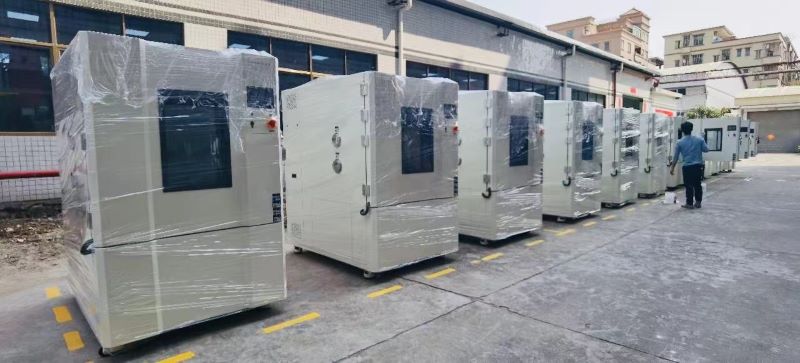
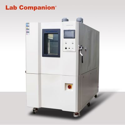
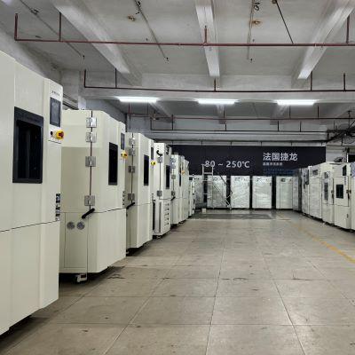
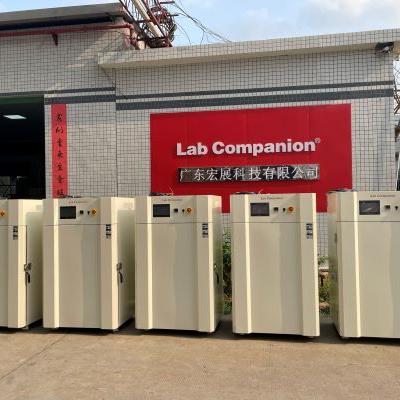
Chambre d'essai de choc thermique :
Il est utilisé pour tester la structure du matériau ou du matériau composite, en un instant dans un environnement continu de température extrêmement élevée et extrêmement basse, le degré de tolérance, de manière à tester les changements chimiques ou les dommages physiques causés par la dilatation et la contraction thermiques. dans les plus brefs délais, les objets applicables incluent le métal, le plastique, le caoutchouc, l'électronique.... Ces matériaux peuvent être utilisés comme base ou référence pour l'amélioration de ses produits.
Le processus de test de choc froid et thermique (choc thermique) peut identifier les défauts de produit suivants :
Coefficient de dilatation différent causé par le dénudage du joint
L'eau entre après fissuration avec un coefficient de dilatation différent
Test accéléré de corrosion et de court-circuit provoqués par une infiltration d'eau
Selon la norme internationale CEI, les conditions suivantes sont des changements de température courants :
1. Lorsque l'équipement est transféré d'un environnement intérieur chaud à un environnement extérieur froid, ou vice versa
2. Lorsque l'équipement est soudainement refroidi par la pluie ou l'eau froide
3. Installé dans les équipements aéroportés extérieurs (tels que : automobile, 5G, système de surveillance extérieur, énergie solaire)
4. Sous certaines conditions de transport [voiture, bateau, air] et de stockage [entrepôt non climatisé]
L’impact de la température peut être divisé en deux types d’impact à deux cases et d’impact à trois cases :
Instructions : L'impact de la température est une méthode courante [haute température → basse température, basse température → haute température], cette méthode est également appelée [impact à deux boîtes], une autre soi-disant [impact à trois boîtes], le processus est [haute température → température normale → basse température, basse température → température normale → haute température], inséré entre la haute température et la basse température, pour éviter d'ajouter un tampon entre les deux températures extrêmes. Si vous regardez les spécifications et les conditions de test, il existe généralement une condition de température normale, les températures hautes et basses seront extrêmement élevées et très basses, dans les spécifications militaires et les réglementations sur les véhicules, vous verrez qu'il existe une condition d'impact de température normale.
Conditions d’essai de choc thermique CEI :
Haute température : 30, 40, 55, 70, 85, 100, 125, 155℃
Basse température : 5, -5, -10, -25, -40, -55, -65℃
Temps de séjour : 10min, 30min, 1h, 2h, 3h (si non précisé, 3h)
Description du temps de séjour du choc thermique :
Le temps de séjour du choc thermique, en plus des exigences de la spécification, dépendra en partie du poids du produit testé et de la température de surface du produit testé.
Les spécifications du temps de séjour du choc thermique en fonction du poids sont :
GJB360A-96-107, MIL-202F-107, EIAJ ED4701/100, JASO-D001... Attendons.
Le temps de séjour du choc thermique est basé sur les spécifications de contrôle de la température de surface : MIL-STD-883K, MIL-STD-202H (air au-dessus de l'objet à tester)
Exigences MIL883K-2016 pour la spécification [choc thermique] :
1. Une fois que la température de l'air atteint la valeur définie, la surface du produit testé doit arriver dans les 16 minutes (le temps de séjour n'est pas inférieur à 10 minutes).
2. Les impacts à haute et basse température sont supérieurs à la valeur définie, mais pas plus de 10 ℃.
Action de suivi du test de choc thermique CEI
Raison : Il est préférable de considérer la méthode d'essai de température CEI dans le cadre d'une série d'essais, car certaines défaillances peuvent ne pas être immédiatement apparentes une fois la méthode d'essai terminée.
Éléments de test de suivi :
Test d'étanchéité IEC60068-2-17
Vibration sinusoïdale IEC60068-2-6
Chaleur humide constante IEC60068-2-78
IEC60068-2-30 Cycle de température chaude et humide
Conditions de test d'impact en température des moustaches d'étain (moustaches) finition :
1. - 55 (+ 0 / -) 10 ℃ s'il vous plaît - 85 (+ / - 0) 10 ℃, 20 min / 1 cycle (vérifiez à nouveau le cycle 500)
1 000 cycles, 1 500 cycles, 2 000 cycles, 3 000 cycles
2. 85(±5)℃←→-40(+5/-15)℃, 20 min/1 cycle, 500 cycles
3.-35 ± 5 ℃ ← → 125 ± 5 ℃, rester pendant 7 min, 500 ± 4 cycles
4. - 55 (+ 0 / -) 10 ℃ s'il vous plaît - 80 (+ / - 0) 10 ℃, 7 min de résidence, 20 min / 1 cycle, 1000 cycles
Caractéristiques du produit de la machine d'essai de choc thermique :
Fréquence de dégivrage : dégivrage tous les 600 cycles [Condition de test : +150 ℃ ~ -55 ℃]
Fonction de réglage de la charge : Le système peut s'ajuster automatiquement en fonction de la charge du produit à tester, sans réglage manuel
Charge de poids élevée : avant que l'équipement ne quitte l'usine, utilisez un circuit intégré en aluminium (7,5 kg) pour la simulation de charge afin de confirmer que l'équipement peut répondre à la demande.
Emplacement du capteur de choc thermique : La sortie d'air et la sortie d'air de retour dans la zone de test peuvent être sélectionnées ou les deux peuvent être installées, ce qui est conforme aux spécifications de test MIL-STD. En plus de répondre aux exigences de la spécification, il est également plus proche de l'effet d'impact du produit testé pendant le test, réduisant ainsi l'incertitude du test et l'uniformité de la distribution.
Test de rupture transitoire du cycle de température de la plaque VMR
Le test de cycle de température est l'une des méthodes les plus couramment utilisées pour tester la fiabilité et la durée de vie des matériaux de soudage sans plomb et des pièces CMS. Il évalue les pièces adhésives et les joints de soudure sur la surface des CMS et provoque une déformation plastique et une fatigue mécanique des matériaux des joints de soudure sous l'effet de fatigue du cycle de température froide et chaude avec une variabilité de température contrôlée, afin de comprendre les dangers potentiels et les facteurs de défaillance. de joints de soudure et CMS. Le diagramme en guirlande est connecté entre les pièces et les joints de soudure. Le processus de test détecte les coupures et les coupures entre les lignes, les pièces et les joints de soudure grâce au système de mesure de rupture instantanée à grande vitesse, qui répond à la demande de test de fiabilité des connexions électriques pour évaluer si les joints de soudure, les billes d'étain et les pièces tombent en panne. Ce test n'est pas vraiment simulé. Son objectif est d'appliquer des contraintes sévères et d'accélérer le facteur de vieillissement sur l'objet à tester pour confirmer si le produit est conçu ou fabriqué correctement, puis d'évaluer la durée de vie en fatigue thermique des joints de soudure des composants. Le test de fiabilité de la connexion électrique à coupure instantanée à grande vitesse est devenu un maillon clé pour assurer le fonctionnement normal du système électronique et éviter la défaillance de la connexion électrique causée par la défaillance du système immature. Les changements de résistance sur une courte période de temps ont été observés lors de changements accélérés de température et d’essais de vibration.
But:
1. S'assurer que les produits conçus, fabriqués et assemblés répondent aux exigences prédéterminées
2. Relaxation de la contrainte de fluage des joints de soudure et de la rupture de rupture CMS causée par la différence de dilatation thermique
3. La température maximale de test du cycle de température doit être inférieure de 25 ℃ à la température Tg du matériau PCB, afin d'éviter plus d'un mécanisme d'endommagement du produit de test de remplacement.
4. La variabilité de la température à 20 ℃/min est un cycle de température, et la variabilité de la température au-dessus de 20 ℃/min est un choc thermique.
5. L'intervalle de mesure dynamique du joint de soudage ne dépasse pas 1 min
6. Le temps de séjour à haute et basse température pour la détermination des défaillances doit être mesuré en 5 coups.
Exigences:
1. Le temps de température total du produit testé se situe dans la plage de la température maximale nominale et de la température minimale, et la durée du temps de séjour est très importante pour le test accéléré, car le temps de séjour n'est pas suffisant pendant le test accéléré. , ce qui rendra le processus de fluage incomplet
2. La température du résident doit être supérieure à la température Tmax et inférieure à la température Tmin.
Se référer à la liste des spécifications :
IPC-9701, IPC650-2.6.26, IPC-SM-785, IPCD-279, J-STD-001, J-STD-002, J-STD-003, JESD22-A104, JESD22-B111, JESD22-B113, JESD22-B117 , SJR-01


 Obtenez un devis
 Réseau IPv6 pris en charge